Base body with soldered-on ground pin, method for its production and uses thereof

a technology of ground pins and base bodies, which is applied in the direction of electrically conductive connections, conductors, electrical apparatus, etc., can solve the problems of difficult control of the size of the region covered on the base body by the solder meniscus and/or the thickness of the solder gap, and the difficulty of further processing there, so as to achieve good microstructural reproducibility and great absorption

Active Publication Date: 2021-12-21
SCHOTT AG
View PDF24 Cites 1 Cited by
  • Summary
  • Abstract
  • Description
  • Claims
  • Application Information

AI Technical Summary

Benefits of technology

[0022]It has been discovered that the microstructuring in the soldering region acts as a solder stop for the metallic solder material. As described, the metallic solder material melts during the soldering process and wets the base body in the soldering region as well as regions of the conductor to be connected to the base body. During the wetting, the solder material runs. Without microstructuring, the running of the solder material is difficult to control. It has been discovered that the micro structuring restricts the running of the melted solder material. In this way, the flow of the metallic solder material can be controlled by the introduction of the microstructuring. Correspondingly, the microstructuring is a solder stop for the metallic solder material. This has the consequence that, in the production of a multiplicity of base bodies in accordance with the present disclosure, the variance of the diameters of the soldering region is less than when there is no microstructuring. By providing a microstructuring in the soldering region in accordance with the present disclosure, the diameter of the soldering region can be reliably controlled. It can at the same time be stated that the restriction of the flow of the solder material does not have to be at the periphery of the microstructuring, but that this restriction is instead already at individual elements of the micro structuring, that is to say as it were in regions within the microstructuring.
[0083]In the case of airbag igniters and / or seatbelt tensioners and / or gas generators, the functional element is a metal pin fixed in the through-opening, like the ground pin soldered to the base body. These metal pins are usually coated with gold, at least in subregions along their axis. The gold coating provides the effect of long-term insensitivity to corrosion and long-term contact. The metal pins are often coated with gold at their end regions. In this way, the region of the metal pin that is within the plug-in connection during assembly for use of the ignition device is gold-coated. In this way, the transfer resistances in the plug-in contact can be reduced.

Problems solved by technology

Similarly, the connection between the earth conductor and the header and / or base body may be damaged or weakened by the fitting of the airbag igniter and / or of a seatbelt tensioner if, for example, the conductors are pushed into a connector and are consequently subjected to mechanical loading.
The size of the region covered on the base body by the solder meniscus and / or the dimensions of the solder gap, including the thickness of the solder gap, is difficult to control.
This leads to the problem for the further processing of the base body that the metallic solder material can get onto the side face of the base body via the edge of the latter and make further processing there more difficult.
If the solder material penetrates between the insulating material in the through-opening and the base body, i.e. generally between the glass of the glazing-in and the outer conductor, there is a great risk of the mechanical strength of the connection of the insulating material within the through-opening to the base body being reduced to a critical extent.
Similarly, a poorly formed solder meniscus and / or solder gap or a poorly formed soldering location can lead to mechanical instabilities of the soldered-on ground pin.
The uncontrolled formation of the solder meniscus and / or solder gap consequently leads to random failures in the bending test.

Method used


Image

  • Base body with soldered-on ground pin, method for its production and uses thereof
  • Base body with soldered-on ground pin, method for its production and uses thereof
  • Base body with soldered-on ground pin, method for its production and uses thereof

Examples


Embodiment Construction

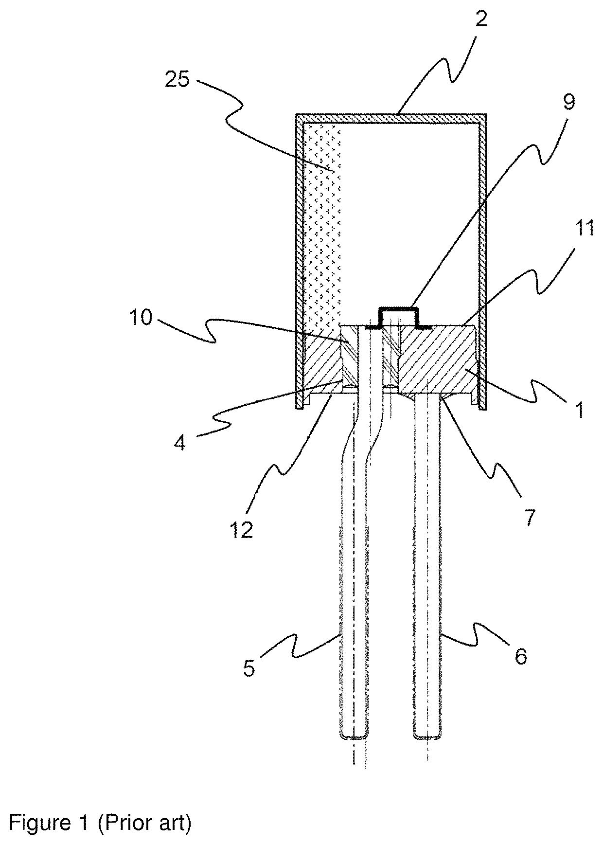
[0102]In FIG. 1, an ignition device known from the prior art for a pyrotechnic protection device is represented, here as an example an airbag igniter. FIG. 1 thereby shows a sectional view of a feed-through element. The feed-through element comprises a metal carrier part with a base body 1, which has a disc-shaped basic form. The feed-through element is often also referred to as a “header element” or “header” for short. In a through-opening 4 of the base body 1, a metal pin 5 is also arranged as a functional element. The through-opening 4 has, in this case, been punched out from the base body 1. The metal pin 5 serves for the contacting of an ignition bridge 9 to supply electrical current, by way of which the propelling charge 25 enclosed in the finished igniter is ignited. The current feed-through in the through-opening 4 is configured as a glass-metal feed-through, glass serving as a fixing material 10 between the metal pin 5 and the wall of the through-opening 4 in the metallic b...


PUM

PropertyMeasurementUnit
depthaaaaaaaaaa
diameteraaaaaaaaaa
widthaaaaaaaaaa

Abstract

The present disclosure relates to components, such as base bodies, for feed-through elements including a metallic base body, at least one through-opening for receiving a functional element in a fixing material, such as an electrically insulating fixing material, and at least one conductor, which is connected electrically conductively to the base body by a soldered connection. The soldered connection includes a metallic solder material that covers a surface region of the base body and thus forms a soldering region on a surface of the base body. The base body has, at least in the soldering region, a microstructuring that includes at least depressions in the surface of the base body. The present disclosure similarly relates to methods for producing such base bodies and to applications thereof.

Description

BACKGROUND OF THE INVENTION1. Field of the Invention[0001]The present disclosure relates to base bodies for feed-through elements in general, for example for feed-throughs for sensors and / or large feed-throughs and / or feed-throughs in transistor-outline packages and / or battery or capacitor feed-throughs, and also to such feed-throughs themselves. Exemplary feed-throughs are for triggering devices, as are used for triggering a pyrotechnic personal protection device, for example in airbag igniters and / or seatbelt tensioners and / or gas generators. The present disclosure relates in particular to the design of the header of such feed-through elements, to the method for its production and to uses thereof.2. Description of the Related Art[0002]Feed-throughs of sensors can supply sensor elements with power and / or pass on their signals to evaluation units. Large feed-throughs are generally used in safety enclosures, for example in liquid gas tanks and / or reactors.[0003]Battery or capacitor f...

Claims


Application Information

Patent Timeline
Patent Type & Authority Patents(United States)
IPC IPC(8): H01L23/045B23K1/20H01L23/488H01L23/492H01L23/10B23K1/00H01L23/14H01L23/29H01R4/02B23K101/38
CPCH01L23/492B23K1/0008B23K1/20H01L23/045H01L23/10H01L23/142H01L23/291H01R4/02B23K2101/38H01R4/028B23K1/005H05K5/0091H01R12/58H01G9/10H01G9/008
Inventor HARTL, HELMUTRANFTL, REINHARD
Owner SCHOTT AG
Why Eureka
Try Eureka