Display module including sweep electrode for controlling PWM pixel circuit and driving method of display module

a display module and sweep electrode technology, applied in static indicating devices, cathode-ray tube indicators, instruments, etc., can solve the problems of deteriorating color reproducibility of images, affecting the accuracy of display,

Active Publication Date: 2021-12-28
SAMSUNG ELECTRONICS CO LTD
View PDF29 Cites 2 Cited by
  • Summary
  • Abstract
  • Description
  • Claims
  • Application Information

AI Technical Summary

Benefits of technology

[0031]As described above, according to various embodiments of the disclosure, a sweep electrode structure capable of uniformly providing a sweep signal may be provided. Therefore, a problem regarding a deviation in luminance due to a deviation in RC load in a sweep electrode in a display module may be solved.

Problems solved by technology

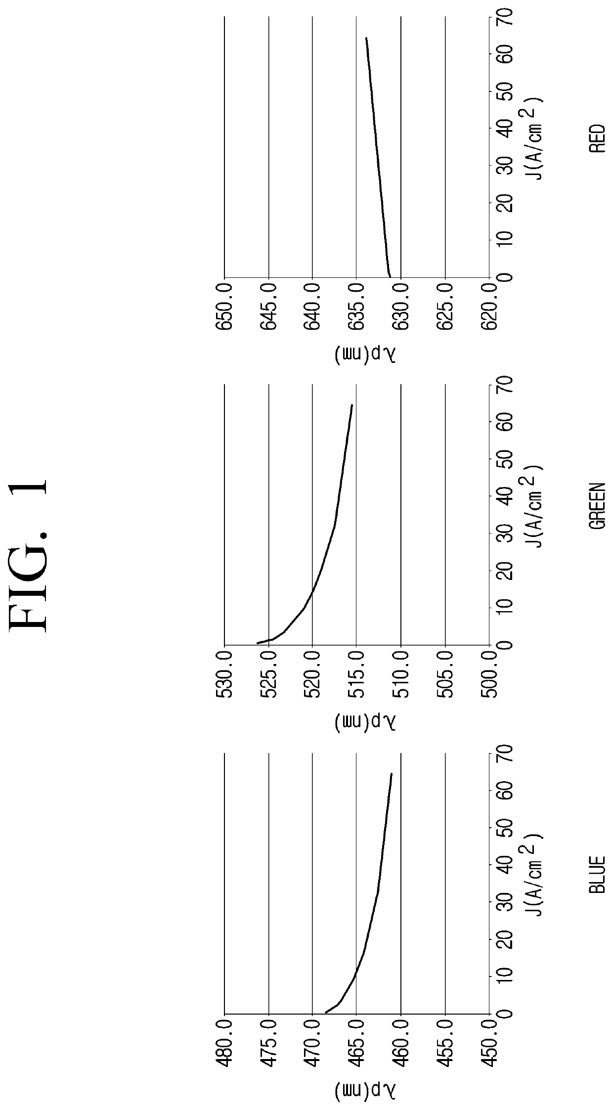
However, in a case of the PAM driving system, not only the gradation of light emitted by the organic light emitting device, but also a wavelength is changed in accordance with the amplitude of the driving current, thereby deteriorating color reproducibility of an image. FIG. 1 shows changes in wavelengths according to a magnitude (or amplitude) of a driving current flowing through a blue LED, a green LED and a red LED.
However, in a case of the digital PWM driving system, the gradation is expressed in a subfield system, thereby incurring a problem regarding false contouring noise, and in a case where the number of subfields is increased to reduce the false contouring problem, a light emitting duty ratio may decrease.
In a case of a display panel of the related art, the sweep signal has not been uniformly applied to a driving transistor due to a deviation in RC load in a sweep electrode, and accordingly, a problem regarding a deviation in luminance has occurred even with the same data voltage.

Method used


Image

  • Display module including sweep electrode for controlling PWM pixel circuit and driving method of display module
  • Display module including sweep electrode for controlling PWM pixel circuit and driving method of display module
  • Display module including sweep electrode for controlling PWM pixel circuit and driving method of display module

Examples


Embodiment Construction

[0053]In describing the disclosure, a detailed description of the related art is omitted when it is determined that the detailed description may unnecessarily obscure a gist of the disclosure. In addition, the overlapping description of the same configuration may be omitted.

[0054]The suffix “part” for an element used in the following description is given or used in consideration of the ease of writing the specification, and does not have a distinct meaning or role as it is.

[0055]The terms used in the disclosure are used to describe an embodiment, but may not intend to limit the scope of other embodiments. Unless otherwise defined specifically, a singular expression may encompass a plural expression.

[0056]It is to be understood that the terms such as “comprise” or “consist of” are used herein to designate a presence of characteristic, number, step, operation, element, part, or a combination thereof, and not to preclude a presence or a possibility of adding one or more of other charac...


PUM

PropertyMeasurementUnit
sizeaaaaaaaaaa
voltageaaaaaaaaaa
sizeaaaaaaaaaa

Abstract

Disclosed is a display module. The display module includes a display panel including an inorganic light emitting device, a sweep electrode connected to at least one input pin, and a pulse width modulation (PWM) pixel circuit, and a driving unit configured to provide a sweep signal to the sweep electrode through the at least one input pin, in which the PWM pixel circuit includes a driving transistor, and provides a driving current having a pulse width corresponding to a data voltage to the inorganic light emitting device by changing a voltage of a gate terminal of the driving transistor according to the sweep signal applied through the sweep electrode, and a number of the at least one input pin varies depending on a size of the display panel.

Description

CROSS-REFERENCE TO RELATED APPLICATIONS[0001]This application claims priority from Korean Patent Application No. 10-2019-0037326, filed in the Korean Intellectual Property Office on Mar. 29, 2019, the disclosure of which is incorporated herein by reference.BACKGROUND1. Field[0002]The disclosure relates to a display module and a driving method of a display module, more particularly, relates to a display module in which a light emitting device constitutes pixels, and a driving method of a display module.2. Description of the Related Art[0003]In the related art, in a display panel in which an inorganic light emitting device such as a red LED, a green LED, or a blue LED constitutes subpixels, gradation of a subpixel has been expressed through a pulse amplitude modulation (PAM) driving system from active matrix driving systems.[0004]The PAM driving system is a system of driving an inorganic light demitting device using a pixel circuit consisting of a transistor and / or a capacitor, and th...

Claims


Application Information

Patent Timeline
Patent Type & Authority Patents(United States)
IPC IPC(8): G09G5/10G09G3/32G09G3/20
CPCG09G3/32G09G3/2003G09G3/2081G09G2300/0421G09G2300/0439G09G2300/08G09G2310/0243G09G2310/06G09G2310/066G09G2320/0223G09G2320/0233G09G2320/064G09G2330/025G09G2320/0247G09G2310/0259G09G2300/0426
Inventor KIM, JINHOSHIN, SANGMINSHIGETA, TETSUYA
Owner SAMSUNG ELECTRONICS CO LTD
Why Eureka
Try Eureka