Subsea installation

a technology for installing subsea components and subsea water, which is applied in the direction of electrical apparatus construction details, electrical apparatus casings/cabinets/drawers, electrical apparatus, etc., can solve the problems of reducing the mechanical cycling lifetime affecting the reliability of the pressure compensator, so as to achieve the effect of long-term reliability and long-term reliability

Active Publication Date: 2021-12-28
ABB (SCHWEIZ) AG
View PDF60 Cites 1 Cited by
  • Summary
  • Abstract
  • Description
  • Claims
  • Application Information

AI Technical Summary

Benefits of technology

[0009]An advantage of the subsea installation of the invention is that it provides a longer pressure compensator lifetime and better reliability.

Problems solved by technology

These processes require large amounts of power that has to be transferred from a remote location at suitable voltages and currents for minimum power loss, to the subsea installations.
Large pressure compensator movements due to large insulation fluid volume variations in a high hydrostatic pressure decrease mechanical cycling lifetime of the pressure compensator.
This, in turn, will generate a need of using a high number of pressure compensators leading to an expensive price of the large subsea installations and other related subsea components.

Method used


Image

  • Subsea installation
  • Subsea installation
  • Subsea installation

Examples


Embodiment Construction

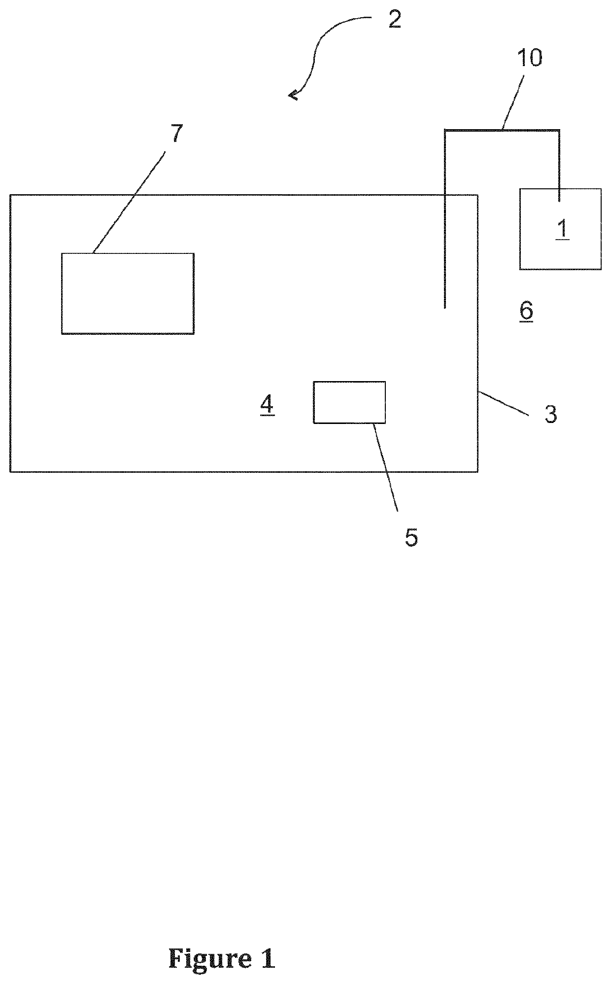
[0017]FIG. 1 shows a pressure compensator 1 of a subsea installation 2. The subsea installation 2 comprises a tank 3 comprising an insulation fluid 4 or other fluid. The pressure compensator 1 is in fluid communication with the tank 3, and the pressure compensator 1 is configured to compensate volume variations of the insulation fluid 4 or the other fluid by performing an expansive and a contracting movement. The subsea installation 1 comprises means for heating 5 the insulation fluid 4 or the other fluid for reducing the volume variations of the insulation fluid 4 or the other fluid.

[0018]The fluid communication between the pressure compensator and the tank 3 may be provided by a connection pipe 10 as shown in FIG. 1. The pressure compensator receives excess insulation fluid 4 from the tank 3 when fluid's temperature and volume increases, and returns the insulation fluid 4 back to the tank 3 when the fluid's 4 temperature and volume decreases.

[0019]The heating of the insulation flu...


PUM

PropertyMeasurementUnit
pressureaaaaaaaaaa
temperatureaaaaaaaaaa

Abstract

A subsea installation. The subsea installation comprises a tank containing an insulation fluid or other fluid, a heat generating electric apparatus positioned at least partly within the tanks, and a pressure compensator being in fluid communication with the tank and being configured to compensate volume variations of the insulation fluid or the other fluid by performing an expansive and a contracting movement. The subsea installation comprises further means for heating the insulation fluid or the other fluid, said means for heating being configured to provide heating to the insulation fluid or the other fluid with the heat generating electric apparatus is in a non-operating state in order to reduce the volume variations of the insulation fluid or the other fluid.

Description

FIELD OF THE INVENTION[0001]The present invention relates to a subsea installation.BACKGROUND OF THE INVENTION[0002]Subsea installations are assemblies comprising several apparatuses used under water. Said assemblies can be installed for example on the bottom ground of a sea. As an example of said subsea installations power transformers used under water can be mentioned. Typically these power transformers comprise a tank filled with insulation and / or cooling fluid to encounter for the high pressure due to deep water depth. Examples of the other subsea liquid filled objects are subsea motors, subsea switchgears, subsea frequency converters, rectifiers and hydraulic store tanks.[0003]The subsea installations are used for example in modern oil and gas production in which the collection, separation, boosting and transport of production fluids takes place on the seabed. These processes require large amounts of power that has to be transferred from a remote location at suitable voltages a...

Claims


Application Information

Patent Timeline
Patent Type & Authority Patents(United States)
IPC IPC(8): H05K5/06F15B21/00H01F27/14F15B1/24H05K7/20
CPCH05K5/068F15B21/006H01F27/14F15B1/24F15B2201/31H05K7/20927H01F27/008H01F27/02H01F38/00
Inventor LAUNONEN, MARKKU
Owner ABB (SCHWEIZ) AG
Why Eureka
Try Eureka