
Balancing reactive current between a DFIG stator and a grid-side inverter

a reactive current and grid-side inverter technology, applied in the direction of reactive power adjustment/elimination/compensation, motors, dynamo-electric machines, etc., can solve the problem of shortening the life of the dfig, and achieve the effect of avoiding unnecessary heating of the dfig

Active Publication Date: 2022-01-25
VESTAS WIND SYST AS
View PDF14 Cites 0 Cited by
  • Summary
  • Abstract
  • Description
  • Claims
  • Application Information

AI Technical Summary

Benefits of technology

The present invention provides a method for reducing the stator current of a DFIG through an abnormal power grid event. By balancing the reactive current between the stator of the DFIG and the grid-side inverter, unnecessary heating of the DFIG can be avoided. This is achieved by keeping the reactive stator current below a predetermined upper stator current limit and the reactive rotor current below a predetermined upper rotor current limit.

Problems solved by technology

This may be disadvantageous in that the increased amount of reactive current may heat the stator to undesired temperatures with the risk of shortening the lifetime of the DFIG.

Method used


Image

  • Balancing reactive current between a DFIG stator and a grid-side inverter
  • Balancing reactive current between a DFIG stator and a grid-side inverter
  • Balancing reactive current between a DFIG stator and a grid-side inverter

Examples


Embodiment Construction

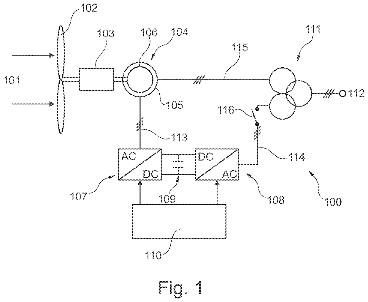
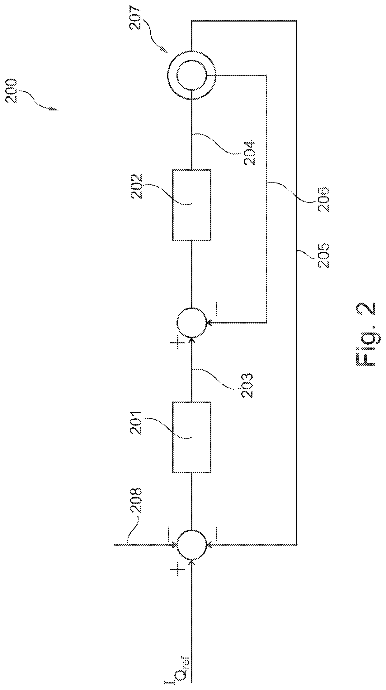
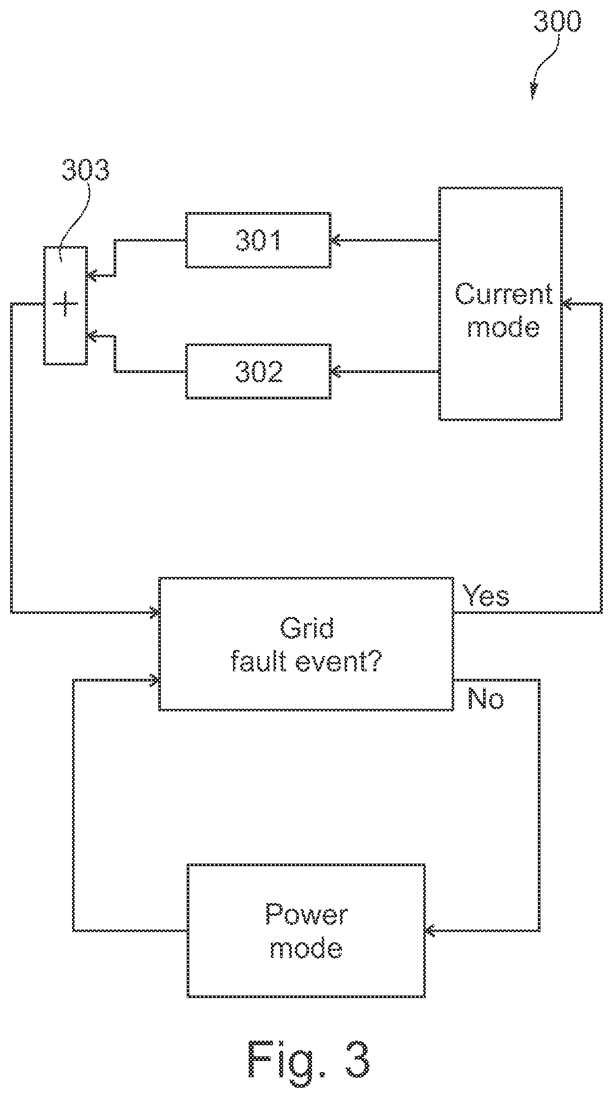
[0027]An aspect of the present invention relates to a method for operating a wind turbine generator using a DFIG during an abnormal power grid event, such as during a power grid voltage drop including an LVRT event, a UVRT event, an OVRT event or an HVRT event. When an abnormal power grid event is detected the generated reactive power is balanced between the stator of the DFIG and a grid-side inverter while taking into consideration an overload current capability of a grid breaker operatively connected to the grid-side inverter. The overload current capability of the grid breaker may be an overload reactive current capability. The overload current capability, or the overload reactive current capability, of the grid breaker may define the conditions at which the grid breaker may be operated above its rated current level.

[0028]Referring now to FIG. 1 a wind turbine generator 100 involving a DFIG 104 is depicted. As seen in FIG. 1 the rotor 106 of the DFIG 104 is coupled to a set of ro...


PUM


Abstract

Aspects of the present invention relate to a method for controlling an amount of reactive current provided from a wind turbine generator to a power grid during an abnormal power grid event, said wind turbine generator comprising a doubly-fed induction generator having a rotor and a stator, and a power converter coupling the rotor to the power grid, the power converter comprising a grid-side inverter, wherein the method comprises the step of balancing the reactive current provided to the power grid between a reactive stator current and a reactive grid-side inverter current, wherein the reactive grid-side inverter current is controlled in accordance with a reactive current capacity of a grid breaker receiving the reactive current provided by the grid-side inverter. Aspects of the present invention also relate to a wind turbine generator being capable of performing the method.

Description

FIELD OF THE INVENTION[0001]Aspects of the present invention relate to a method and a wind turbine generator for balancing reactive power between a stator of a doubly-fed induction generator and a grid-side inverter during an abnormal power grid event.BACKGROUND OF THE INVENTION[0002]During an abnormal power grid event, it may be necessary to increase the amount of reactive current delivered to the power grid. In case the power producing unit involves a wind turbine generator applying a doubly-fed induction generator (DFIG), the majority of reactive current is delivered to the power grid via the stator of the electrical generator.DESCRIPTION OF ASPECTS OF THE INVENTION[0003]In known arrangements involving DFIGs the increased amount of reactive current is delivered via the stator. This may be disadvantageous in that the increased amount of reactive current may heat the stator to undesired temperatures with the risk of shortening the lifetime of the DFIG. Thus, there is a need for a m...

Claims


Application Information

Patent Timeline
Patent Type & Authority Patents(United States)
IPC IPC(8): H02J3/18F03D7/02F03D9/25G05B15/02H02K7/18H02P9/00
CPCH02J3/1892F03D7/0284F03D9/255G05B15/02H02K7/183H02P9/007H02P2207/073Y02E40/30H02J3/18F05B2270/1071Y02E10/72Y02E10/76
Inventor BIRIS, CIPRIANMERRILD, UFFE C.CHRISTENSEN, LEIF SVINTHANDERSEN, GERT KARMISHOLT
Owner VESTAS WIND SYST AS
Learn More