Image processing device, image processing method, and image display system
a technology of image display and image processing, applied in the direction of electric digital data processing, instruments, computing, etc., can solve the problems of increased cost, non-satisfactory display standard requirements, and image not being displayed normally, and achieve effective and effective display area
- Summary
- Abstract
- Description
- Claims
- Application Information
AI Technical Summary
Benefits of technology
Problems solved by technology
Method used
Image
Examples
first embodiment
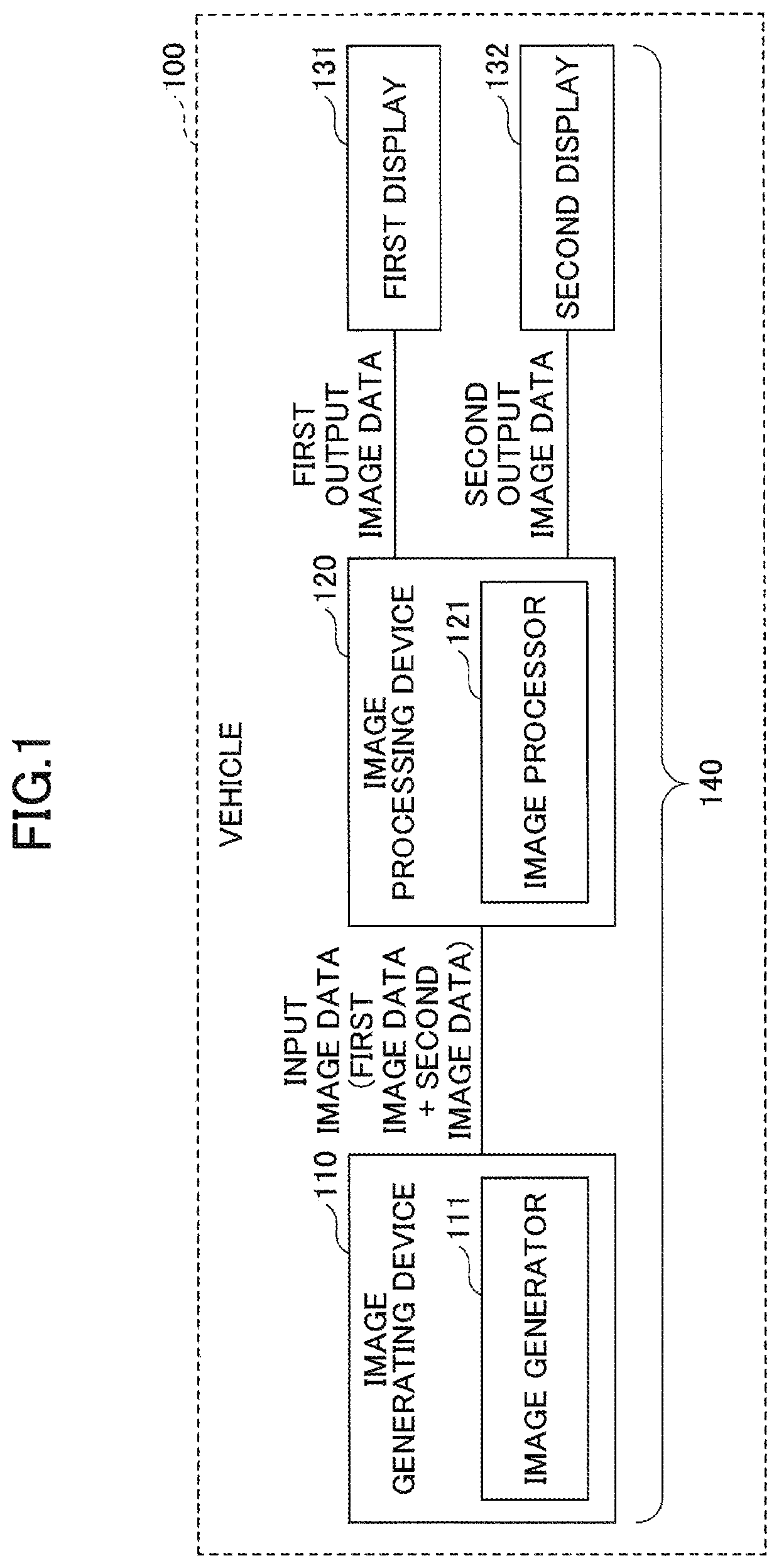
[0025]First, a system configuration of an in-vehicle image display system is described. FIG. 1 is a drawing illustrating an example of a system configuration of an in-vehicle image display system.
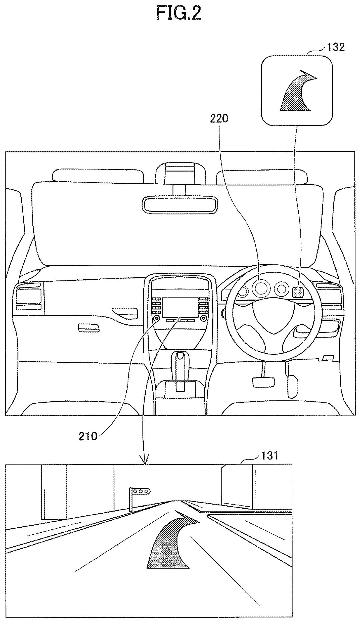
[0026]As illustrated in FIG. 1, an image display system 140 installed in a vehicle 100 includes an image generating device 110, an image processing device 120, a first display 131, and a second display 132.
[0027]The image generating device 110 is, for example, a navigation device or a head unit in an in-vehicle system, and includes an image generator 111 (generating unit). The image generator 111 generates input image data based on first image data for the first display 131 and second image data for the second display 132, and outputs the input image data to the image processing device 120.
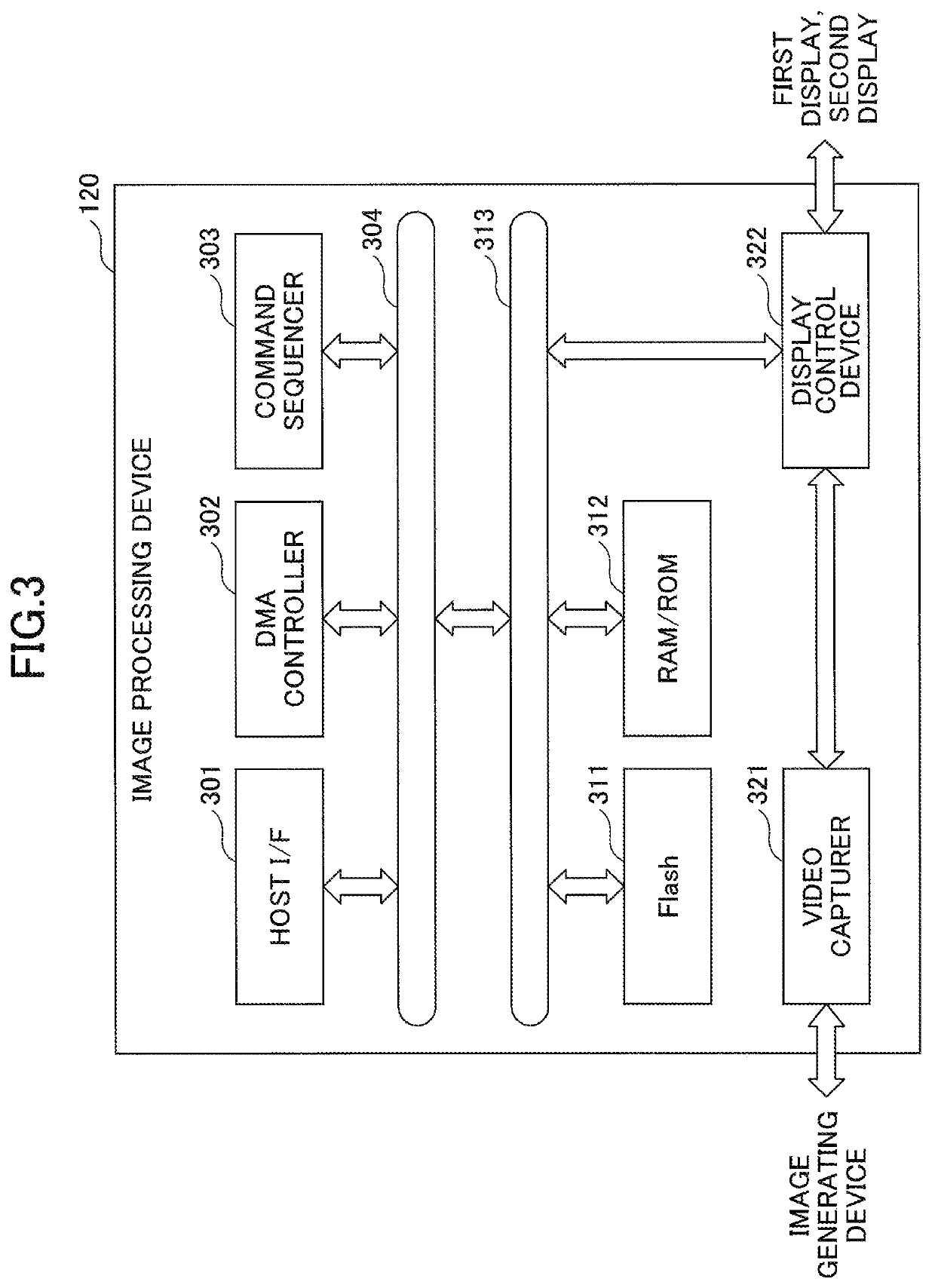
[0028]For example, a semiconductor chip for executing image processing is provided in the image processing device 120, and the image processing device 120 functions as an image processor 121 implemented b...
second embodiment
[0113]In the configuration of the first embodiment, the scaler performs a filtering process to reduce the number of lines of an effective display area. On the other hand, in a second embodiment, the scaler performs a thinning process to reduce the number of lines of an effective display area. Below, differences between the second embodiment and the first embodiment are mainly described.
(1) Details of Processes Performed by Devices
[0114]First, details of processes performed by devices in an image display system 140 of the second embodiment are described. FIG. 8 is a drawing illustrating details of processes performed by devices in the image display system of the second embodiment.
[0115]The image generating device 110 generates image data 511 by combining, in the horizontal direction, an effective display area 511-1 of first image data for the first display 131 having a resolution of 1920 pixels×1080 pixels and an effective display area 511-2 of second image data for the second displa...
third embodiment
[0152]In the first embodiment, the scaler performs a filtering process to reduce the number of lines of an effective display area; and in the second embodiment, the scaler performs a thinning process to reduce the number of lines of an effective display area.
[0153]On the other hand, in a third embodiment, the scaler shifts the wrapping position of each line to change the aspect ratio and thereby reduce the number of lines of an effective display area. Below, differences between the third embodiment and the first and second embodiments are mainly described.
(1) Details of Processes Performed by Devices
[0154]First, details of processes performed by devices in an image display system 140 of the third embodiment are described. FIG. 11 is a drawing illustrating details of processes performed by devices in the image display system of the third embodiment.
[0155]The image generating device 110 generates image data 511 by combining, in the horizontal direction, an effective display area 511-1...
PUM
 Abstract
Description
Claims
Application Information
 - R&D
- Intellectual Property
- Life Sciences
- Materials
- Tech Scout
- Unparalleled Data Quality
- Higher Quality Content
- 60% Fewer Hallucinations
Browse by: Latest US Patents, China's latest patents, Technical Efficacy Thesaurus, Application Domain, Technology Topic, Popular Technical Reports.
© 2025 PatSnap. All rights reserved.Legal|Privacy policy|Modern Slavery Act Transparency Statement|Sitemap|About US| Contact US: help@patsnap.com


