Flight control system for an aircraft

a flight control and aircraft technology, applied in the field of aircraft flight control systems, can solve the problems of low probability of loss of availability of auto-pilot laws, and inability to implement secondary computers

Active Publication Date: 2022-02-15
AIRBUS OPERATIONS (SAS)
View PDF13 Cites 0 Cited by
  • Summary
  • Abstract
  • Description
  • Claims
  • Application Information

AI Technical Summary

Benefits of technology

[0012]Thus, by virtue of this flight control system, given that all the main computers are configured to implement auto-pilot laws, the auto-pilot mode is continuously available during the normal operation of the aircraft. The aircraft pilot is thus relieved of the responsibility of monitoring the operation of the auto-pilot. Using main computers from two hardware types avoids a failure mode common to all of the main computers. The fact that the main computers of the first hardware type are configured to control the actuators as per a first tolerance level and that the main computers of the second hardware type are configured to control the actuators as per a second tolerance level, less stringent than the first tolerance level, allows the actuators to be controlled by the main computers of the first hardware type with a high level of precision when these main computers of the first hardware type are operational. In the event of the failure of the main computers of the first hardware type, the main computers of the second hardware type allow the actuators to be controlled with a lower precision level, due to the less stringent tolerance level. In return, this less stringent tolerance level improves the availability of the main computers of the second hardware type. This improvement in the operational availability of the main computers helps to implement auto-pilot laws in all the main computers, while using a limited number of computers. In the main computers of the second hardware type, the risk of failure due to the complexity of the auto-pilot laws is reduced by the use of a less stringent tolerance level than the first tolerance level used in the main computers of the first hardware type.
[0028]In particular, the actuators of the set of actuators are distributed between the first sub-set of actuators and the second sub-set of actuators in such a way that, for a rudder of the aircraft belonging to a sub-set of rudders referred to as critical rudders, a first actuator associated with this rudder forms part of the first sub-set of actuators and a second actuator associated with this rudder forms part of the second sub-set of actuators. Advantageously, the various actuators of the set of actuators are distributed between the first sub-set of actuators and the second sub-set of actuators in such a way that the actuators of the first sub-set of actuators alone allow the flight of the aircraft to be controlled and the actuators of the second sub-set of actuators alone allow the flight of the aircraft to be controlled;

Problems solved by technology

As a result, the auto-pilot laws, due to their complexity, cannot be implemented in the secondary computers.
Furthermore, for autonomous airplane or drone type aircraft, the probability of the loss of availability of the auto-pilot laws needs to be extremely low, for example, below 1×10⁻⁹ per flight hour.

Method used


Image

  • Flight control system for an aircraft
  • Flight control system for an aircraft
  • Flight control system for an aircraft

Examples


Embodiment Construction

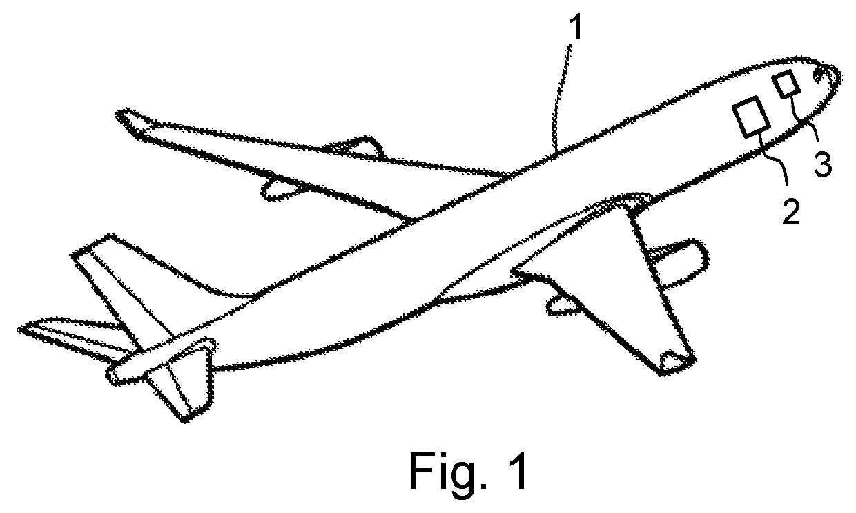
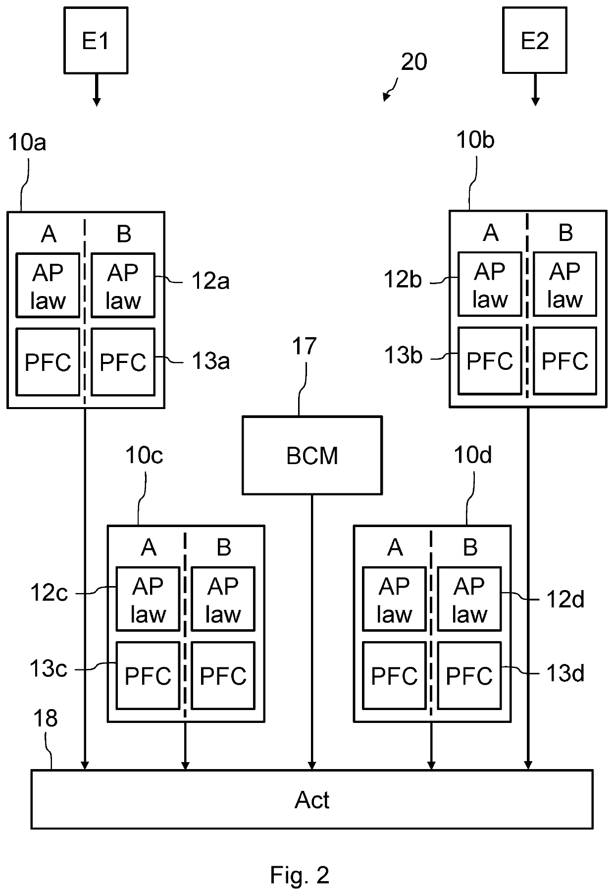
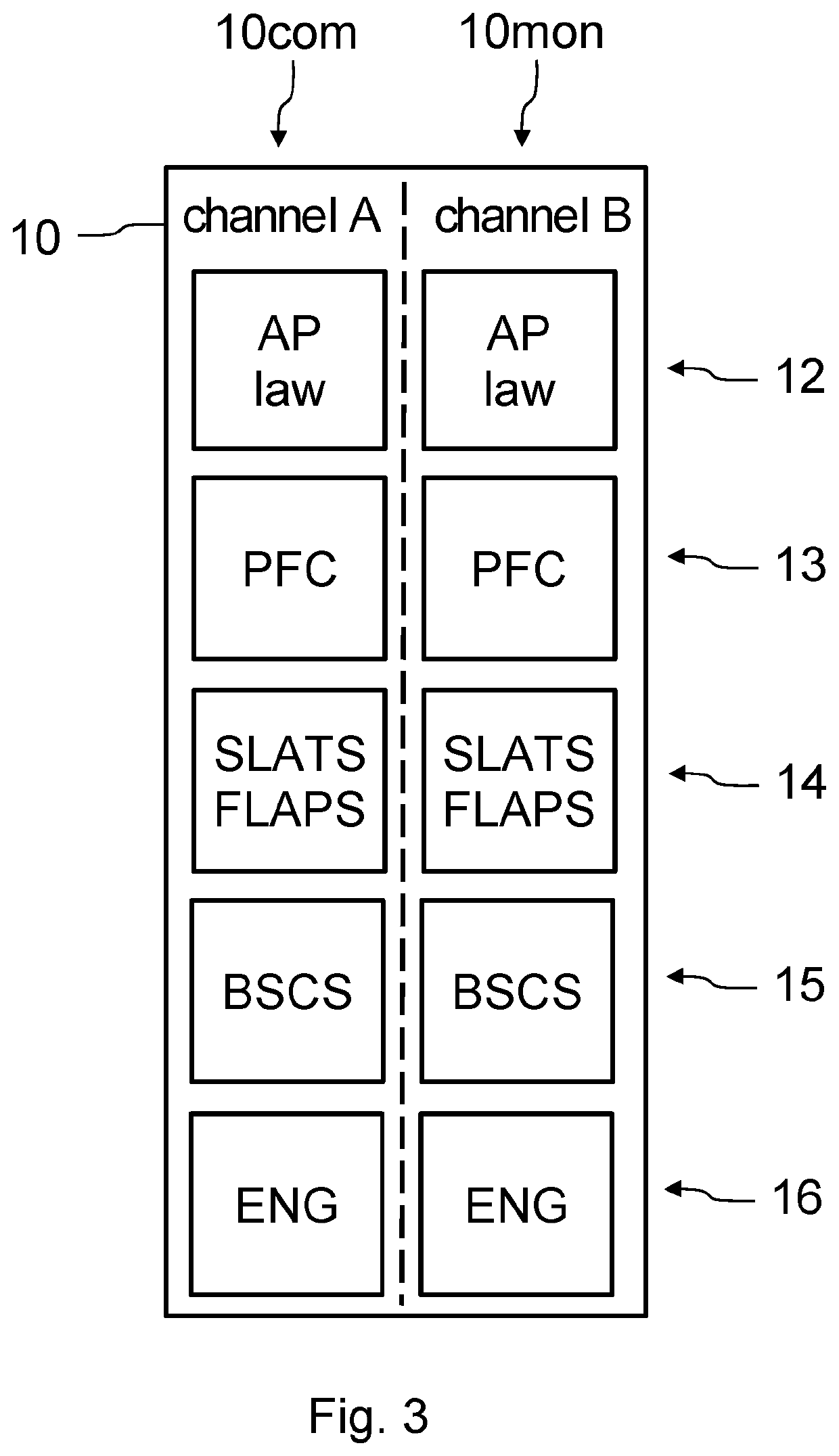
[0041]The aircraft 1 shown in FIG. 1 comprises a flight control system, such as the flight control system 20 shown in FIG. 2. This flight control system comprises a set of flight control computers and a set 18 of actuators for controlling the aircraft, denoted Act in the figure. The set of flight control computers is only made up of a set of computers, called main computers 10a, 10b, 10c, 10d, and of at least one backup computer 17 (denoted BCM (Backup Control Module) in the figure). These computers are located, for example, in an avionics bay 2 of the aircraft, near the cockpit 3. Each of the main computers is of the duplex type, i.e., it comprises two similar modules, denoted channel A and channel B in the figure. Each function implemented by the main computer is duplicated on each of the channels A and B, with one of the channels acting in control mode (COM) and the other acting in monitor mode (MON). This allows monitoring of the COM / MON type to be conducted, during which monito...


PUM


Abstract

A flight control system for an aircraft comprises a set of actuators for controlling the aircraft and a set of flight control computers only made up of a set of duplex type main computers and of at least one backup computer. All the main computers are configured to implement auto-pilot laws for the aircraft. The set of main computers comprises two computers from a first hardware type, configured to control actuators of the set of actuators as per a first tolerance level and two computers from a second hardware type, different from the first hardware type, configured to control actuators of the set of actuators as per a second tolerance level, less stringent than the first tolerance level.

Description

CROSS-REFERENCES TO RELATED APPLICATIONS[0001]This application claims the benefit of the French patent application No. 1871824 filed on Nov. 26, 2018, the entire disclosures of which are incorporated herein by way of reference.FIELD OF THE INVENTION[0002]The invention relates to a flight control system for an aircraft designed to particularly control the rudders of the aircraft.BACKGROUND OF THE INVENTION[0003]Modern aircraft, in particular transport airplanes, comprise a set of flight control computers that compute orders for controlling actuators of rudders of the aircraft. These rudders are, for example, flaps or ailerons located on the wings of the aircraft, elevators located, for example, on a stabilator at the rear of the aircraft, a rudder located on the fin, etc. The flight control computers are different and redundant so that the flight control system is reliable faced with failures that are likely to affect some computers. Furthermore, in general, some of the computers are...

Claims


Application Information

Patent Timeline
Patent Type & Authority Patents(United States)
IPC IPC(8): G01C23/00G05D1/00G05D3/00G06F7/00G06F17/00B64C13/50B64C13/18G06F15/16
CPCB64C13/505B64C13/18G05D1/0077G06F15/161B64C19/02G05B9/03B64C13/503
Inventor FERVEL, MARC
Owner AIRBUS OPERATIONS (SAS)
Why Eureka
Try Eureka