Operating mode optimization for electric propulsion system with downsized DC-DC converter

a technology of electric propulsion system and operating mode optimization, which is applied in the direction of dc-ac conversion without reversal, battery/cell propulsion, transportation and packaging, etc., can solve the problems of size-proportionate electrical losses within the converter and its associated power electronic components, electrical losses also occur within the individual semiconductor switches of the converter, etc., to improve the overall drive performance of the electric propulsion system, reduce the proportionate reduction of losses of the inductor coil, and optimize energy efficiency

Active Publication Date: 2022-02-22
GM GLOBAL TECH OPERATIONS LLC
View PDF15 Cites 0 Cited by
  • Summary
  • Abstract
  • Description
  • Claims
  • Application Information

AI Technical Summary

Benefits of technology

[0005]The controller regulates ongoing operation of the TPIM / electric machine and the buck-boost converter using a loss map, e.g., a set of lookup tables programmed in memory of the controller. Using the present method, a DC output voltage of the converter is controlled to a minimum loss voltage selected from the loss map. The controller is thus able to optimize the energy efficiency and improve the overall drive performance of the electric propulsion system.
[0006]As will be appreciated by those of ordinary skill in the art, in order to ensure responsive operation of an electric machine at peak power levels, an electric propulsion system ordinarily incorporates a DC-DC converter sized and rated to match the peak power requirement. However, sizing to the peak power requirement results in electrical losses within the converter and its associated power electronic components. For example, size-proportionate electrical losses occur within a relatively massive inductor coil of the DC-DC converter. Downsizing of the inductor coil proportionately reduces such losses. Likewise, a capacitor bank used as part of the converter hardware may be similarly downsized. Electrical losses also occur within the individual semiconductor switches of the converter, albeit to a lesser extent. The present converter is therefore downsized relative to the typical peak power-based alternative, e.g., from about 90-100 kW to about 20-30 kW in an exemplary embodiment.
[0011]The bypass switch may be controlled in such a way as to balance the voltage across the bypass switches, i.e., the output voltage of the battery pack (“battery voltage”) and the DC bus voltage. The bypass switch may be optionally embodied as a mechanical relay to help minimize component cost, and to minimize internal resistance when the bypass switch is in an ON / conducting state. It is desirable to immediately close the bypass switch when the voltage across the bypass switch is balanced. However, a typical opening time of a mechanical relay is on the order of 5-10 ms. Therefore, PWM control over designed converter switches may be used in certain embodiments to properly balance the voltage across the bypass switch as set forth herein.
[0013]A method for controlling the electric propulsion system includes calculating, via a controller, a required output power from the converter based on a requested operating mode, a commanded speed, and a commanded torque of the electric machine. The method also includes comparing the required output power to a calibrated power threshold, and controlling the converter via the controller. Control of the DC-DC converter includes, when the required output power exceeds the calibrated power threshold, closing the bypass switch via the controller to thereby bypass the converter. When the required output power is less than the calibrated power threshold, the controller determines a minimum loss voltage from a loss map, and thereafter uses the minimum loss voltage as a target control voltage of the converter to thereby optimize efficiency of the electric propulsion system.

Problems solved by technology

However, sizing to the peak power requirement results in electrical losses within the converter and its associated power electronic components.
For example, size-proportionate electrical losses occur within a relatively massive inductor coil of the DC-DC converter.
Electrical losses also occur within the individual semiconductor switches of the converter, albeit to a lesser extent.

Method used


Image

  • Operating mode optimization for electric propulsion system with downsized DC-DC converter
  • Operating mode optimization for electric propulsion system with downsized DC-DC converter
  • Operating mode optimization for electric propulsion system with downsized DC-DC converter

Examples


Embodiment Construction

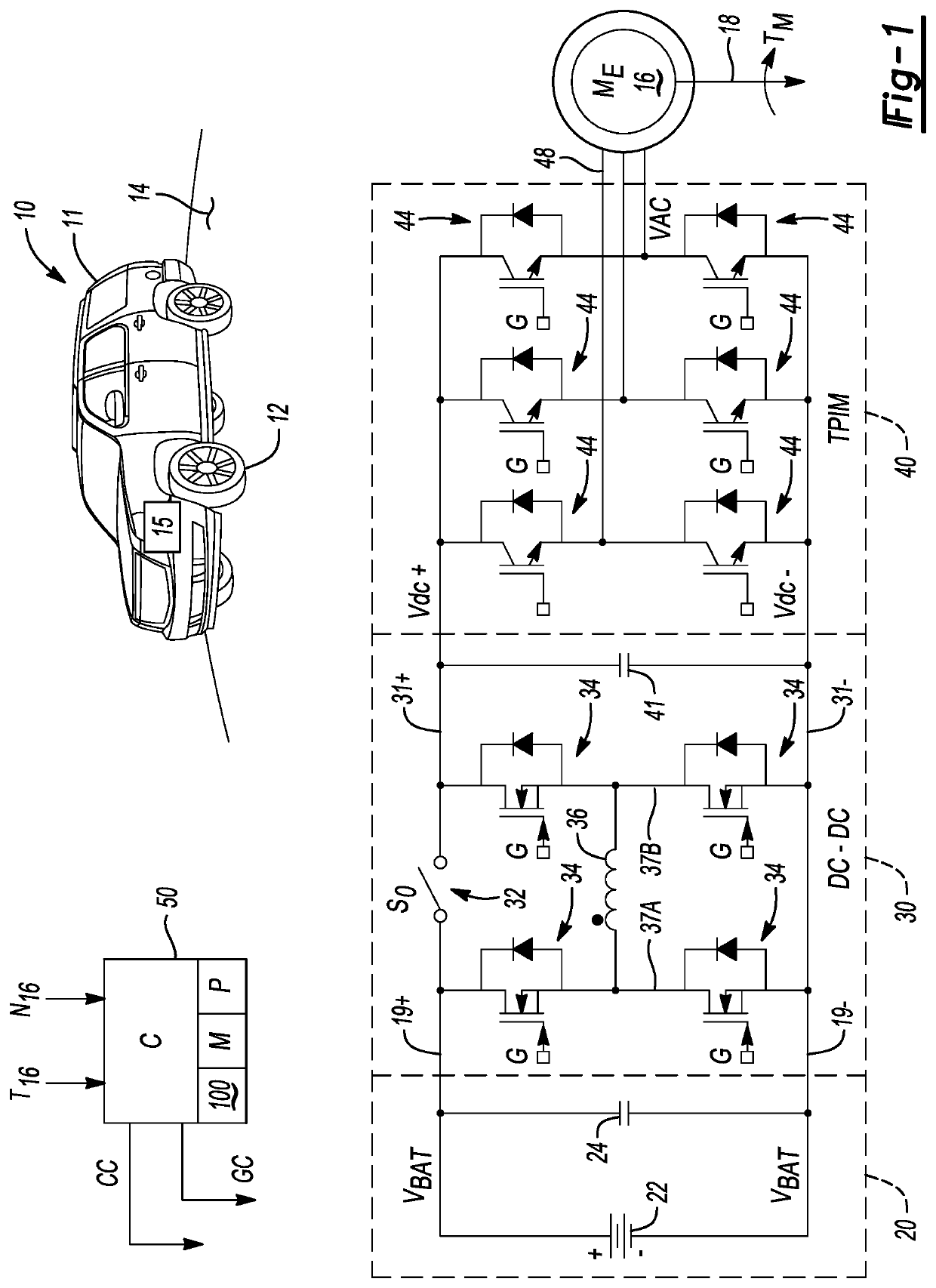
[0021]Referring to the drawings, wherein like reference numbers refer to like components throughout the several views, FIG. 1 depicts a mobile platform 10 having a body 11 and an electric propulsion system 15. The mobile platform 10 may be optionally embodied as a motor vehicle, a robot, etc., and thus equipped in such embodiments with road wheels 12 in rolling contact with a road surface 14. While the mobile platform 10 is one possible example of a system benefitting from the electric propulsion system 15, other beneficial applications for the electric propulsion system 15 may also be envisioned, including but not limited to stationary power plants, mobile platforms, and other types of land, air, or marine vehicles.

[0022]The electric propulsion system 15 includes a polyphase electric machine (“ME”) 16 having a rotatable output shaft 18. When the electric machine 16 is energized via application of a polyphase / alternating current voltage (“VAC”) to individual phase windings 48 of the...


PUM


Abstract

An electric propulsion system includes a battery pack and a DC-DC converter. The converter has a bypass switch and semiconductor switches. A traction power inverter module (“TPIM”) rectifies a DC bus voltage on the voltage bus to produce an AC bus voltage. An electric machine is connected to the TPIM and energized via the AC bus voltage. A controller calculates required output power from the converter based on a requested operating mode, and speed and torque of the electric machine. When the output power exceeds a threshold, the bypass switch closes to bypass the converter. When the output power is less than the threshold, the controller uses a minimum loss voltage from a loss map as a target control voltage of the converter to optimize efficiency of the electric propulsion system.

Description

INTRODUCTION[0001]Electric propulsion systems rely on torque that is generated by one or more rotary electric machines and directed to a coupled load. Electric machines are often configured as polyphase / alternating current (“AC”) devices that are energized by a direct current (“DC”) voltage bus and battery pack. A power inverter module is therefore used as part of the electric propulsion system to either invert or rectify an input voltage, with the particular operation performed by the power inverter module being dependent on the present operating mode.[0002]During a regenerating operating mode, for instance, control over the ON / OFF conducting states of individual inverter switches located within the power inverter module is used to rectify an AC input voltage from the electric machine when operating as a generator, with the power inverter module producing a DC output voltage. The DC output voltage is thereafter used to recharge constituent battery cells of the above-noted battery p...

Claims


Application Information

Patent Timeline
Patent Type & Authority Patents(United States)
IPC IPC(8): B60L50/64B60L15/20
CPCB60L50/64B60L15/2045B60L2210/12B60L2210/14B60L2240/421B60L2240/423B60L2240/427H02M3/1582H02M7/48H02M1/32H02P27/08B60L15/007B60L53/24H02M3/158H02M7/53871H02M1/007H02M1/0048Y02T10/64Y02T10/70Y02T10/72Y02T10/7072Y02T90/14
Inventor HAO, LEINAMUDURI, CHANDRA S.GOPALAKRISHNAN, SURESHDUAN, CHENGWUBUCKNOR, NORMAN K.
Owner GM GLOBAL TECH OPERATIONS LLC
Why Eureka
Try Eureka