Liner and load assembly therefor

a technology of liner and load assembly, applied in the field of machine for container closure, can solve the problems of speed limitation of conventional rotary liner design and damage to can end, and achieve the effects of reducing the force applied, increasing production volume, and increasing speed

Active Publication Date: 2022-02-22
STOLLE MACHINERY
View PDF12 Cites 0 Cited by
  • Summary
  • Abstract
  • Description
  • Claims
  • Application Information

AI Technical Summary

Benefits of technology

[0007]These needs and others are met by embodiments of the disclosed concept, which are directed to a liner and load assembly therefor. Among other advantages, the load assembly reduces forces applied to can ends, thereby allowing the line to operate at greater speeds and increased production volumes.

Problems solved by technology

Among other limitations, conventional rotary liner designs suffer from speed limitations in order to avoid damage to the container closures being processed.
However, known load assembly components, such as for example and without limitation, existing star wheel and downstacker designs, are known to cause damage to can ends if speeds are increased beyond the foregoing (e.g., without limitation, great than about 262.5 rpm at the turret).

Method used


Image

  • Liner and load assembly therefor
  • Liner and load assembly therefor
  • Liner and load assembly therefor

Examples


Embodiment Construction

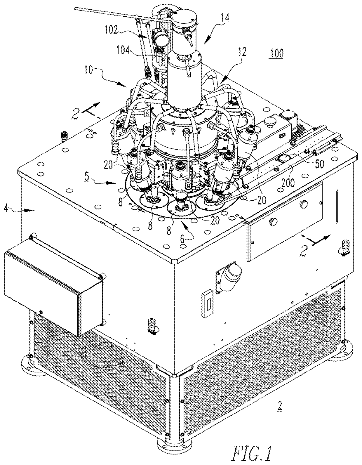
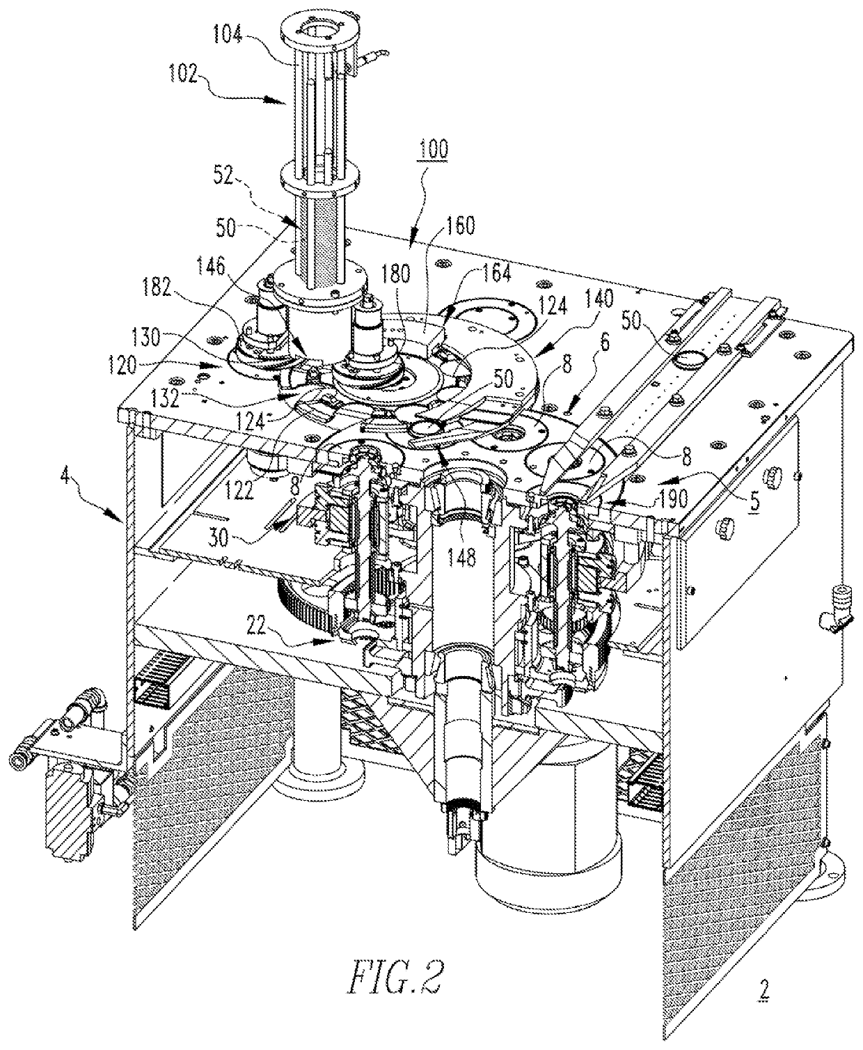
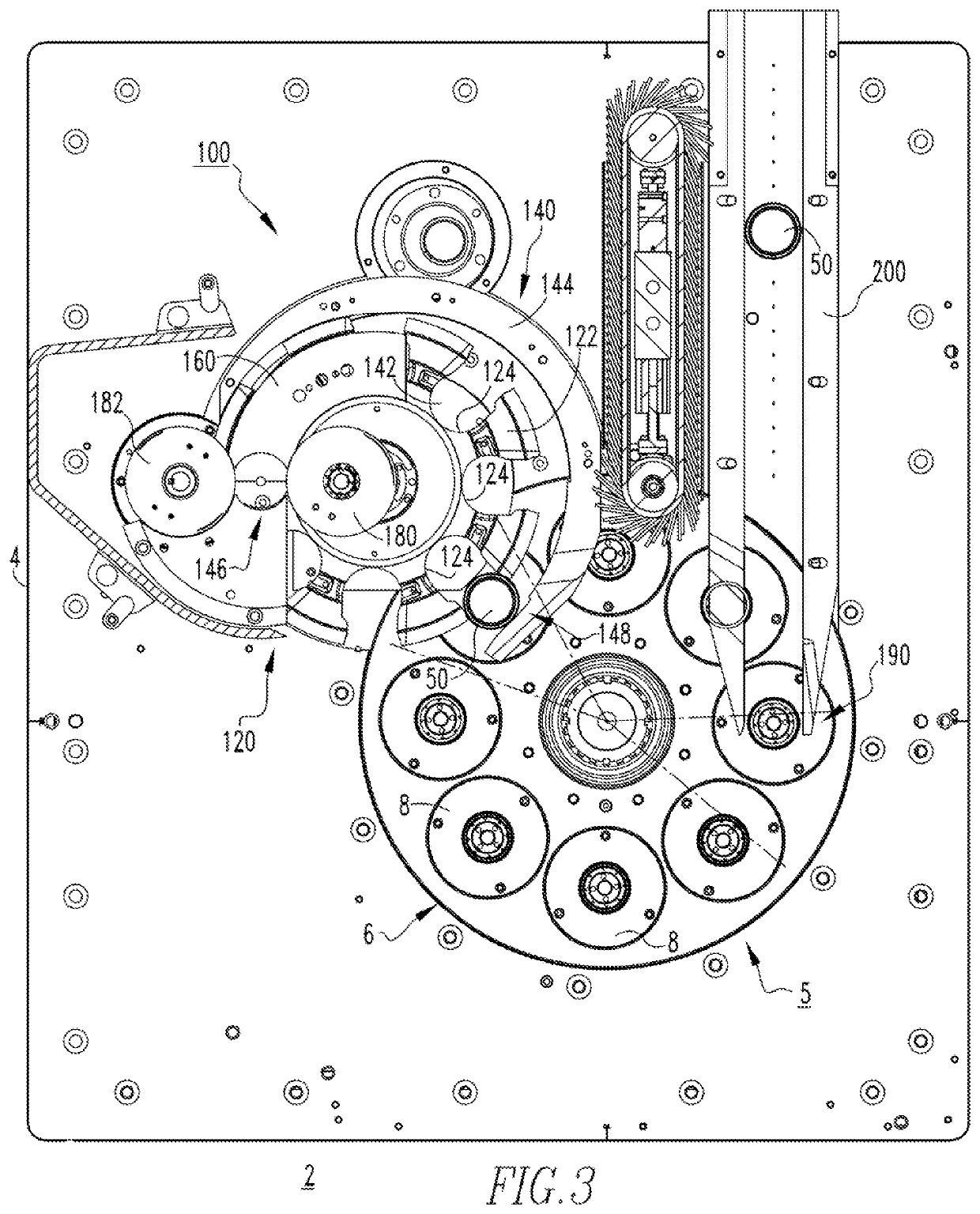
[0028]It will be appreciated that although a load assembly in accordance the disclosed concept is shown and described herein as used with respect to a rotary liner for applying a sealant or compound to container closures, it could alternatively be employed to convey container closures with a wide variety of other types of equipment and machines (not shown) in other applications.

[0029]Directional phrases used herein, such as, for example, up, down, clockwise, counterclockwise and derivatives thereof, relate to the orientation of the elements shown in the drawings and are not limiting upon the claims unless expressly recited therein.

[0030]The specific elements illustrated in the drawings and described herein are simply exemplary embodiments of the disclosed concept. Accordingly, specific dimensions, orientations and other physical characteristics related to the embodiments disclosed herein are not to be considered limiting on the scope of the disclosed concept.

[0031]As employed herein...


PUM


Abstract

A load assembly includes a supply mechanism structured to supply a plurality of container closures, and a conveyance assembly comprising a star wheel including a number of load pockets structured to receive the container closures and move the container closures from the supply mechanism to a processing assembly. The star wheel has an outer perimeter. Each of the load pockets is structured to receive a corresponding one of the container closures inboard of the outer perimeter of the star wheel.

Description

BACKGROUNDField[0001]The disclosed concept relates generally to machinery for container closures and, more particularly, to liners for applying a coating material to container closures such as, for example, can ends. The disclosed concept also relates to load assemblies for liners.BACKGROUND INFORMATION[0002]It is known to apply sealant material, commonly referred to as compound, to the underside of container closures, for example, to facilitate subsequent sealing attachment (e.g., without limitation, seaming) of the closures to containers such as, for example, beer / beverage and food cans.[0003]A rotary liner machine, for example, is used to line (i.e., apply sealant or compound) to container closures, commonly referred to as can lids, shells or can ends, at relatively high speed in relatively high volume applications. The rotary liner generally includes a base having a chuck assembly. A pivotal upper turret assembly is disposed over the chuck assembly and includes an electrical tan...

Claims


Application Information

Patent Timeline
Patent Type & Authority Patents(United States)
IPC IPC(8): B65G47/84B05B13/02
CPCB65G47/846B05B13/0242B65G2201/0252B67B3/062B05B9/01
Inventor ZUMBERGER, NEIL ALBERTALBRIGHT, STEVEN TODDSTAMMEN, DENNIS CORNELIUS
Owner STOLLE MACHINERY
Why Eureka
Try Eureka