Permanent below ground flood barrier installation

a flood barrier and installation technology, applied in the field of permanent below ground flood barriers, can solve the problems of insufficient protection, insufficient flood barrier, and insufficient protection of existing levees, and achieve the effects of ensuring stability and weight of flood barriers, easy removal of components, and convenient deploymen

Active Publication Date: 2022-02-22
HUGHES CHRISTOPHER T
View PDF8 Cites 2 Cited by
  • Summary
  • Abstract
  • Description
  • Claims
  • Application Information

AI Technical Summary

Benefits of technology

[0012]The instant invention provides a permanent installation that may be hidden from view below ground level. A trench may be dug into the ground around the area to be protected. A concrete foundation or permanent ballast may be poured into the bottom of the full length and width of the trench to provide secure stability and weight to the flood barrier. Interconnected modules in the form of an elongated housing may be anchored into the trench by bolts secured into the concrete ballast. The housing may contain the components of the flood barrier, i.e., a water impermeable membrane wall the lower end of which may be affixed to the housing and a series of foldable support structures to maintain the membrane wall. The interconnected modules may together provide a single water proof container, the housing, around the area to be protected, and sections, or panels, of the water impermeable membrane may likewise be connected together to form the continuous water impermeable membrane wall. When deployed, the foldable support structures may be removed from the housing and anchored at ground level to rest behind the membrane wall. The installation may have a protective cover that can be removed easily to expose the components and may be utilized by being placed atop the anchored supports and have the upper end of the water impermeable membrane wall affixed thereto. Just as the concrete ballast may provide the security anchor for the flood barrier wall, the additional anchors may provide security for the support structures to insure that they withstand the considerable water pressures, high winds, and storm surges that may come. No special skills may be necessary to erect the flood barrier wall once the installation has been completed since all necessary components may be present within the housing to be easily deployed without the need for any tools.
[0016]It is a further object of the instant invention to install the modules into a trench dug into the ground surrounding the area to be protected and to further have a poured concrete base along the bottom of the full length and width of the trench to create a strong foundation and sufficient ballast to anchor and prevent any displacement of the modules due to the forces of the flood waters or storm surges.
[0017]Another object of the instant invention is to provide means to securely affix the modules to the concrete ballast to prevent any uplift or separation of the modules or of the flood barrier when confronted by strong water forces and surges.
[0018]A still further object of the instant invention is to provide anchoring means to securely hold the support structures in place at ground level behind the membrane wall so that the membrane wall and supports cannot be distorted or toppled during the onslaught of flood conditions.
[0022]A further object of the instant invention is to provide a flood barrier installation that can be installed and function well in large cities as well as rural and seashore areas and is only dependent upon the accessibility of the area to prepare the trench in which the ballast and the modules are permanently installed.
[0024]The present invention is also a permanent below ground flood barrier installation to protect a specified area when flood waters are imminent which comprises a trench surrounding the area to be protected, the trench having a bottom surface, a concrete ballast disposed along the bottom surface of the full length of the trench, a housing the length of the trench disposed above the concrete ballast and anchored to it, the housing having an interior, means for anchoring the housing to the ballast so that the housing is not contiguous with it, a flexible water impermeable fabric wall foldably contained within the housing and extendable upward to protect the area when flood waters are imminent, the fabric wall having an upper edge and a lower edge, a series of supports having a horizontal upper edge contained within the housing, the supports to be set at ground level to maintain the fabric wall when extended upward, and a removable cover to protect the interior of the housing and its contents when not in use against flood waters and to form an integral part of the flood barrier. There are also means for affixing the lower edge of the fabric wall to the housing so that the flood waters cannot enter the housing or pass beyond the fabric wall and means for affixing the upper edge of the fabric wall to the cover so that the cover can be set on the horizontal upper edges of the supports to sustain the upward extended fabric wall, whereby the fabric wall is secured at the lower edge to the housing and the upper edge to the supported cover to form the completed flood barrier and the flood waters cannot pass therebeyond.

Problems solved by technology

Flooding caused by rising waters has been a problem for mankind since the beginning of recorded time.
Existing levees may no longer be sufficient to protect property and buildings and sandbags require considerable time and transport of materials and may also be insufficient protection.
During Hurricane Sandy in 2012 New York City experienced damage from salt water that had never before been a problem.
Each step requiring much time and manpower.
Sand used to hold back flood waters can no longer be returned to beaches and playgrounds.
This system must be installed when the building is constructed and is only practical for buildings of limited circumference.
Neither of these inventions would be practical with waters exhibiting any significant force or height.
Therefore, any strong force or storm surge could easily topple or uproot the posts or uproot the entire mounting plate.
This system is not designed for high water or storm surges.
Though each of the prior art disclosures exhibits interesting concepts and advantages, none will sustain the onslaught of the high waters and strong water surges now becoming more frequent in the changing world of which we are all a part.
Many advantages of permanent installations were shown by the prior art, but looking at features from each, none exhibit the means to withstand a storm surge of any major impact.
The systems with floatable barriers are only good if a flood stems from a rising lake during a spring thaw and neither has any real ground anchor.
Most of the barriers discussed above have flex and mobility but lack sufficient support or ground anchor to withstand any significant forces.
Often by the time a flood warning is sent out the weather may already be bad slowing transportation and impacting outdoor working conditions.

Method used


Image

  • Permanent below ground flood barrier installation
  • Permanent below ground flood barrier installation
  • Permanent below ground flood barrier installation

Examples


Embodiment Construction

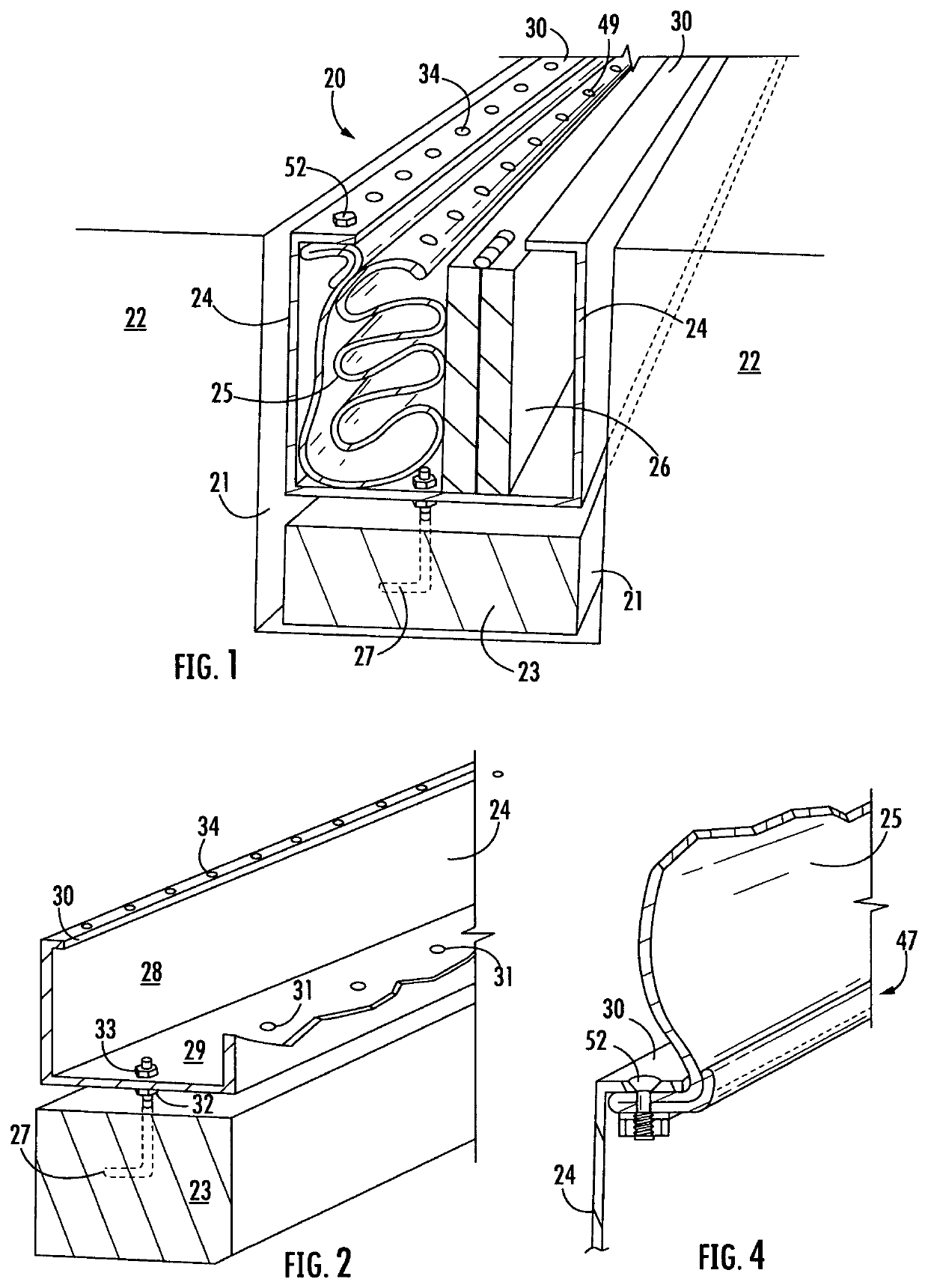
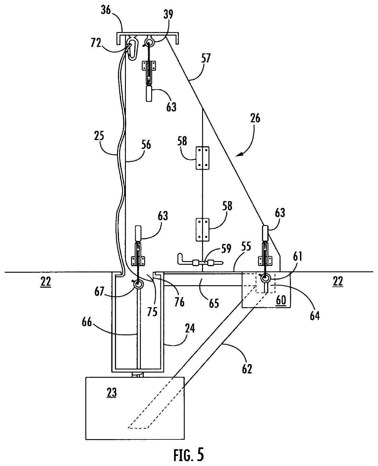
[0039]The flood barrier assembly 20 provided by the instant invention consists of six basic components, a trench 21 dug into the ground 22 to surround the area to be protected, a poured concrete ballast 23 running the full length of the trench 21, a housing 24 disposed within the trench 21 above the ballast 23 and connected thereto, a flexible and water impermeable membrane wall 25, foldable supports 26 to shore up the membrane wall 25, the latter two components to be stored within the housing 24, and a cover 36 for the housing 24. This may seem an oversimplification, but may clearly indicate that once in place, these few components may offer the necessary protection to property in the face of severe weather. All components except the cover 36 may be seen in FIG. 1.

[0040]The flood barrier installation first requires a site-plan carefully constructed after a thorough topographical survey of the property or access to FEMA maps showing the infra structure of the land to be protected as...


PUM


Abstract

A permanent below-ground flood barrier installation is characterized by a trench surrounding a specified area. A concrete ballast lines the trench and anchors a covered housing containing a flexible water impermeable fabric wall and a series of supports. When a flood is impending the housing is opened, the supports removed and set up vertically at ground level, and the fabric wall extended upward. The fabric wall is attached at its upper edge to the cover set atop the supports, and at its lower edge to the housing. Three point anchoring of the supports maintain them in vertical orientation and stop means prevent backward movement during storm surges. When flooding subsides the components can be cleaned, dried and returned to the housing. No tools or special skills are required to set up the wall and supports once the initial installation has been completed.

Description

[0001]This application contains the same material disclosed in a Provisional Patent application Ser. No. 63 / 103,707 filed on Aug. 21, 2020. The information regarding the Provisional Patent is contained in the Application Data Sheet submitted herewith.FIELD OF THE INVENTION[0002]The instant invention relates to a permanent below-ground installation in the form of a continuous trench of substantial depth with a concrete ballast extending the full length and width of the trench, to surround an area to be protected and to provide a secure anchor for a housing containing a flexible flood barrier wall and wall supports that can be erected quickly by unskilled persons to function as a levee or retaining wall to protect against rising waters during flood conditions. The housing and flexible wall can be made in connectable water impermeable units of any desired length and contour to conform to the line of the installation. After the flood waters have receded the barrier wall and supports can...

Claims


Application Information

Patent Timeline
Patent Type & Authority Patents(United States)
IPC IPC(8): E04H9/14E02B3/10
CPCE04H9/145E02B3/102Y02A50/00
Inventor HUGHES, CHRISTOPHER T.
Owner HUGHES CHRISTOPHER T
Why Eureka
Try Eureka