Sealing device and medical device with at least one sealing device

a sealing device and sealing technology, applied in the direction of hose connections, couplings, pipe couplings, etc., can solve the problems of limited free positioning of gas removal points for removing combustible gases, and achieve the effect of convenient device construction, compact structure shape, and convenient handling and mounting

Active Publication Date: 2022-02-22
DRAGERWERK AG
View PDF34 Cites 0 Cited by
  • Summary
  • Abstract
  • Description
  • Claims
  • Application Information

AI Technical Summary

Benefits of technology

[0009]The advantage of the present invention is that the sealing device portion with the sealing device portion volume between the first sealing point and the second sealing point collects gas possibly escaping between the line element and the coupling element and encloses the line element and the coupling element in a gas-tight manner. A fire or explosion hazard due to escaping gas is thus avoided with certainty, since gas flowing out cannot enter the area of electrical or electronic circuits or consumers. Based on the fact that avoidance of the fire and explosion hazard is achieved, a coupling element acting as a gas removal point can be positioned, in principle, as desired, i.e., for example, also in the vicinity in space of electrical or electronic circuits or consumers. This facilitates the construction of devices, for example, medical devices, especially medical devices in the form of medical supply units, which comprise at least one gas removal point, and it makes possible, for example, a more compact structural shape, because no special distance has to be maintained between a gas removal point and electrical or electronic circuits or consumers.
[0010]In one embodiment of the gas-tight sealing device, the sealing device portion is manufactured in one piece with the first sealing point and the second sealing point from a material acting as a seal at the sealing point edges, for example, from an elastomer. The resulting flexibility of the sealing device portion facilitates the handling and mounting thereof. The one-piece configuration avoids the use of an otherwise necessary seal and thus likewise facilitates the handling and mounting.
[0011]In another embodiment of the gas-tight sealing device, the sealing device portion has a vent port between the first sealing point and the second sealing point. A pressure equalization between the interior of the sealing device and the surrounding area as well as removal of gas collected by means of the sealing device are possible via the vent port. A line element in the form of a flexible tube or the like may be connected to the vent port in order to release the gas collected during a removal at a location at which the gas would not cause any fire or explosion hazard.
[0012]In a special embodiment of the gas-tight sealing device, the sealing device portion is configured geometrically and in terms of construction in such a manner that a compact structural shape requiring only a small volume will be obtained. Provisions are made for this for the sealing device portion not to enclose any additional components aside from the coupling element or the part of the coupling element as well as the part of the line element. The walls of the sealing device portion can thus tightly adjoin the outer surfaces of the coupling element and of the line element. Such a compact structural shape leads to a gas removal point with a surrounding sealing device portion requiring only an insignificantly larger space for installation of the of the gas-tight sealing device than a gas removal point without such a of the gas-tight sealing device. This facilitates the construction of devices, especially medical devices with at least one gas removal point enclosed by means of a gas-tight sealing device with a sealing device portion of the type here and hereinafter described.
[0013]Another aspect of the invention comprises a medical device, especially a medical device acting as a medical supply unit, with at least one coupling element and with a line element connected to the coupling element, wherein at least one part of the coupling element as well as at least one section of the line element are enclosed by means of a gas-tight sealing device with a sealing device portion of the type here and hereinafter described.
[0014]An exemplary embodiment of the present invention will be explained below in more detail. Mutually corresponding objects or elements are designated by the same reference numbers in all figures.

Problems solved by technology

Free positioning of gas removal points for removing combustible gases is greatly limited hereby, since the positioning of a gas removal point is no longer possible, for example, above a power outlet by the definition of the size of the leakage.

Method used


Image

  • Sealing device and medical device with at least one sealing device
  • Sealing device and medical device with at least one sealing device
  • Sealing device and medical device with at least one sealing device

Examples


Embodiment Construction

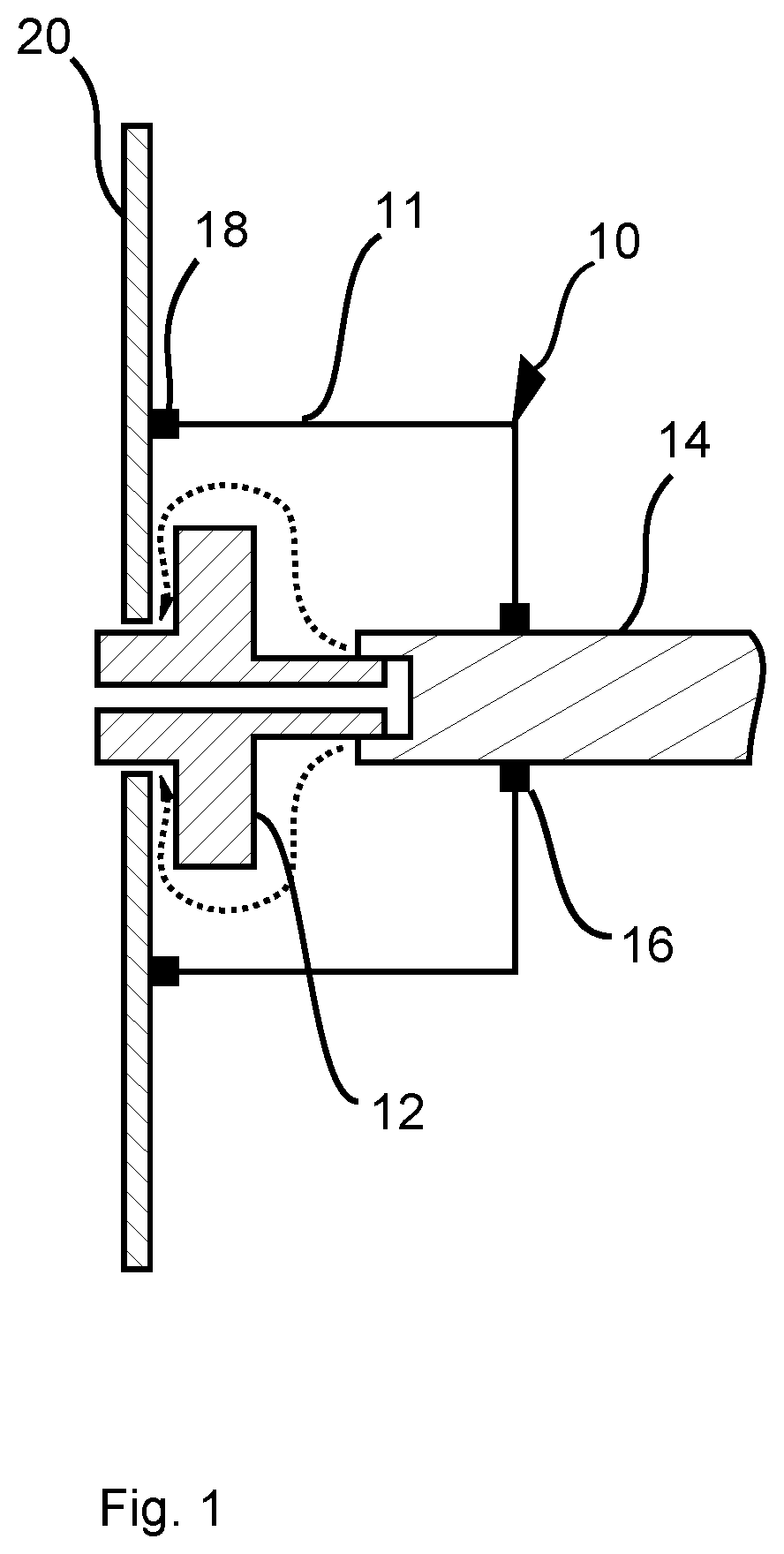
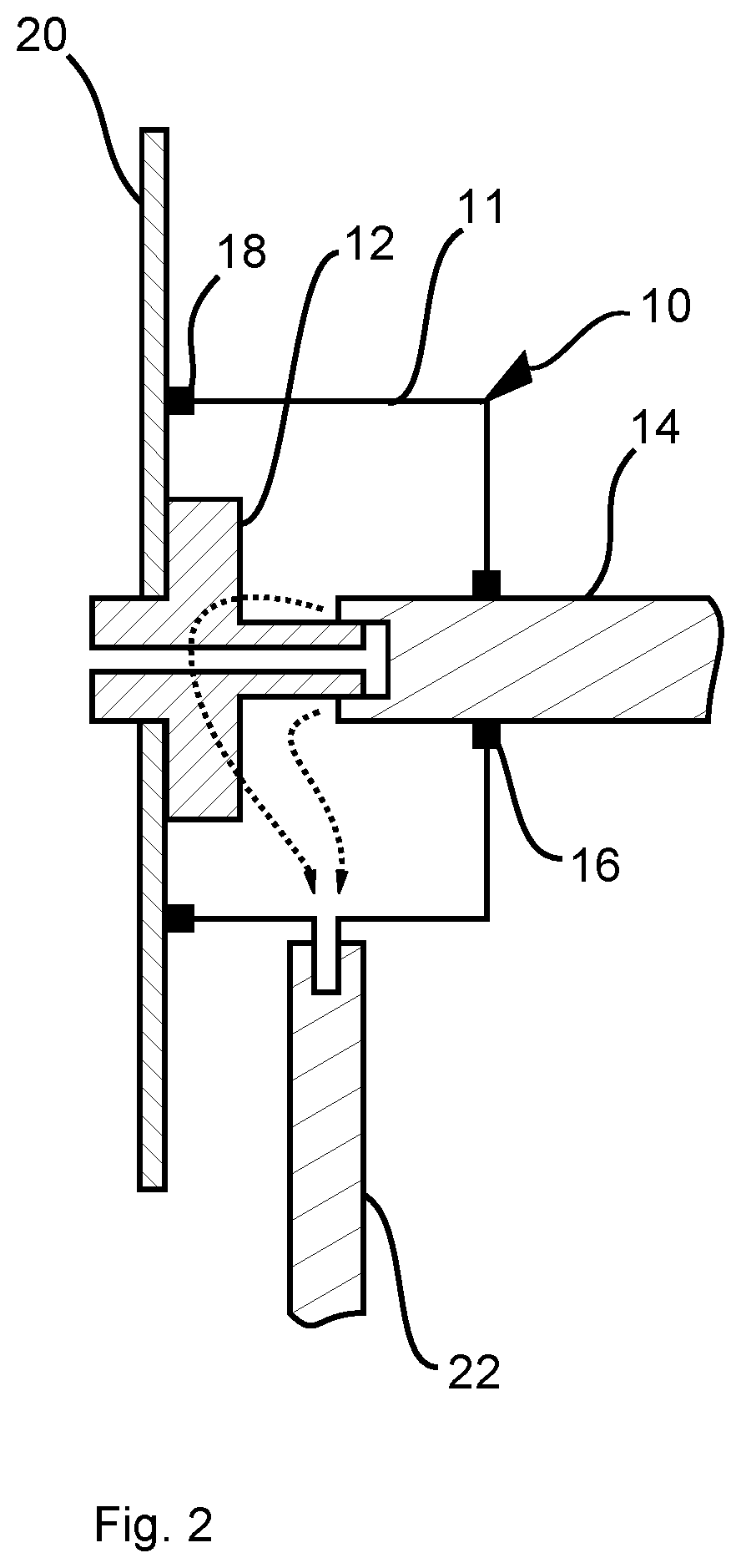
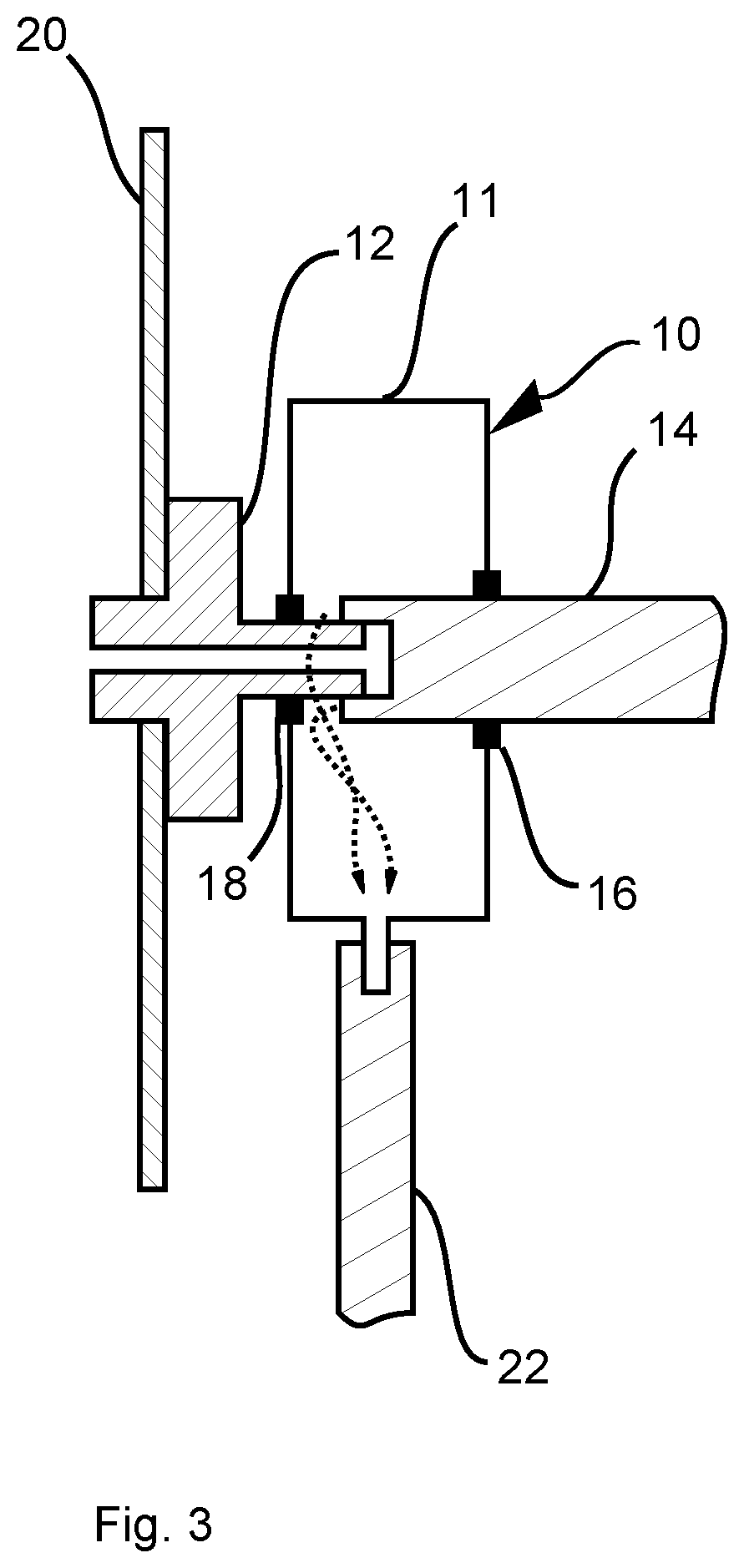
[0022]Referring to the drawings, the view in FIG. 1 shows an embodiment of a particular a gas-tight sealing device generally designated 10, shown in a schematically simplified sectional view. The gas-tight sealing device 10 comprises a sealing device portion (a wall / barrier that is gas impermeable) 11, which gas-tightly encloses a coupling element 12 acting, for example, as a removal point (gas removal point) for combustible gas, especially a coupling element 12 in the form of or configured as a tube connection bushing, as well as a section of a line element 14 connected to the coupling element 12, i.e., for example, a section of a flexible tube. The gas-tight sealing device 10 adjoins for this the line element 14, extending all around in a gas-tight manner, at a first sealing point (sealing edge) 16, and the gas-tight sealing device 10 comprises for this, for example, a seal, which is in contact with the outer surface of the line element 14 in the area of the first sealing point 16...


PUM


Abstract

A gas-tight sealing device (10) encloses at least one part of a coupling element (12) as well as at least one section of a line element (14) connected to the coupling element (12). The the gas-tight sealing device (10) comprises a sealing device portion or wall (11) that adjoins a first sealing point and a second sealing point (16, 18). The sealing device portion or wall (11) extends around, in a gas-tight manner, the line element (14) and the coupling element (12) or a wall (20), or a further line element, in or at which the coupling element (12). The gas-tight sealing device (10) encloses a volume defined by the geometry of the sealing device portion (11) in a gas-tight manner between the first sealing point (16) and the second sealing point (16, 18).

Description

CROSS REFERENCE TO RELATED APPLICATIONS[0001]This application claims the benefit of priority under 35 U.S.C. § 119 of German Application 10 2017 009 674.0, filed Oct. 17, 2017, the entire contents of which are incorporated herein by reference.TECHNICAL FIELD[0002]The present invention pertains to a connection point between a coupling element and a line element connected to the coupling element as well as to a device for sealing the connection point (sealing device). The coupling element is, for example, a coupling element acting as a gas removal point.BACKGROUND[0003]Corresponding to applicable standards, gas areas are to be separated in space—among other things, in medical technology—from electronic or electrical areas. This applies especially to medical supply units. Such a specification is based on the circumstance that, for example, an increased oxygen concentration may lead to a fire or an explosion in conjunction with electrical potentials.[0004]To separate a gas area from ele...

Claims


Application Information

Patent Timeline
Patent Type & Authority Patents(United States)
IPC IPC(8): F16L3/04F16L19/02F16L5/10A61M16/08F16L3/01F16L19/04
CPCF16L19/0225A61M16/08A61M16/0875F16L3/01F16L3/04F16L5/10F16L19/043F16L2201/20F16L2201/44F16J15/06F16L5/02F16L33/18
Inventor ELFRING, ROBERTJÄKE, CHRISTIANMARTIN, THOMAS
Owner DRAGERWERK AG
Why Eureka
Try Eureka