
Magnetic disk substrate, method for manufacturing same and magnetic disk

a technology of magnetic disk and substrate, which is applied in the field of magnetic disk substrate, magnetic disk substrate, and method of fabricating magnetic disk substrate, can solve the problems of large disk flutter, large disk flutter, and rapid rotating magnetic disk vibration, etc., and achieve the effect of effectively reducing deficiencies and improving fluttering characteristics

Active Publication Date: 2022-03-08
FURUKAWA SKY ALUMINUM CORP +1
View PDF13 Cites 0 Cited by
  • Summary
  • Abstract
  • Description
  • Claims
  • Application Information

AI Technical Summary

Benefits of technology

The patent describes a way to make a magnetic disk substrate that has better resistance to fluttering (which is when the substrate bends too much during operation) and has fewer defects on its surface. This method makes it possible to create a more reliable and efficient magnetic disk.

Problems solved by technology

Unfortunately, an aluminum alloy substrate for a magnetic disk having such a smaller thickness has a lower rigidity.
In addition, in a high-speed HDD, magnetic disks receive increased exciting forces due to large fluid forces generated by rapid rotation of the magnetic disks, and thus cause large disk flutters.
That is, the rapidly rotating magnetic disks vibrate (flutter) due to unstable airflows generated between the magnetic disks.
The magnetic disks composed of aluminum alloy substrates having a low rigidity cause large vibration, so that a magnetic head, which is a reading unit, cannot readily follow such vibration of the magnetic disks, thereby increasing the frequency of errors in positioning of the magnetic head.
As well as the improvement in fluttering characteristics, a reduction in deficiencies on the surface of the base electroless plating layer is also required, which has been a typical problem.
Such deficiencies on the base plating layer lead to deficiencies on the magnetic disk, such as pits.
These deficiencies and their surrounding regions cannot be used for reading and wiring of data.

Method used


Image

  • Magnetic disk substrate, method for manufacturing same and magnetic disk
  • Magnetic disk substrate, method for manufacturing same and magnetic disk

Examples


examples

[0121]Examples of the disclosure will now be described in more detail but should not be construed as limiting the disclosure.

[0122]In the casting step, materials were melted to prepare a molten aluminum alloy having each of the compositions shown in Table 1. This molten aluminum alloy was casted by the DC casting method to produce an aluminum alloy ingot.

[0123]The resulting ingot was subject to facing on both surfaces at a thickness of 15 mm and then homogenized at 520° C. for one hour. The ingot was then hot rolled at an initial temperature of 460° C. and a final temperature of 280° C. to produce a hot rolled plate having a thickness of 3.0 mm.

[0124]The hot rolled plate was then cold rolled (at a reduction ratio of 73.3%) to produce an aluminum alloy plate having a thickness of 0.8 mm. In the punching step, the aluminum alloy plate was punched to yield an annular disk blank having an outer diameter of 96 mm and an inner diameter of 24 mm.

[0125]The disk blank was then subject to pre...


PUM

PropertyMeasurementUnit
thicknessaaaaaaaaaa
depthaaaaaaaaaa
timeaaaaaaaaaa

Abstract

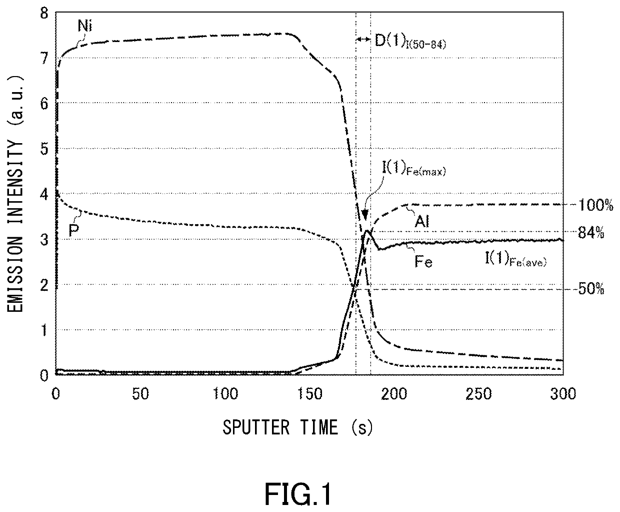
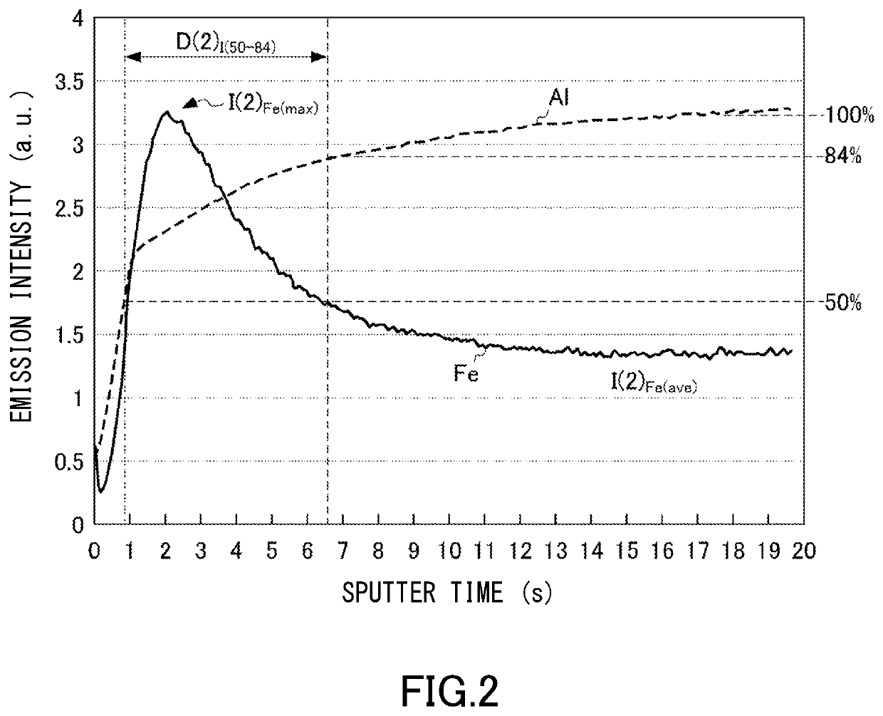
A magnetic disk substrate is composed of an aluminum alloy substrate, a base plating layer on a surface of the aluminum alloy substrate, and a boundary region between the aluminum alloy substrate and the base plating layer. The boundary region includes a specific boundary region (D(1)I(50-84)) having Al emission intensities equal to 50% to 84% of an average Al emission intensity in an interior region of the aluminum alloy substrate in glow discharge optical emission spectroscopy in the depthwise direction from the surface of the magnetic disk substrate. The specific boundary region (D(1)I(50-84)) has a maximum Fe emission intensity (I(1)Fe(max)) higher than an average Fe emission intensity (I(1)Fe(ave)) in the interior region of the aluminum alloy substrate in the glow discharge optical emission spectroscopy.

Description

[0001]This is a National Phase Application filed under 35 U.S.C. § 371, of International Application No. PCT / JP2018 / 043879, filed Nov. 28, 2018, the contents of which are incorporated by reference.TECHNICAL FIELD[0002]The present disclosure relates to a magnetic disk substrate, a method of fabricating the magnetic disk substrate, and a magnetic disk.BACKGROUND ART[0003]Aluminum-alloy magnetic disk substrates applied to storages of devices, such as computers and data centers, are composed of substrates having excellent mechanical characteristics and processability as well as good plating characteristics. For example, a magnetic disk substrate is composed of a substrate based on the 5086 alloy (aluminum alloy containing 3.5 mass % or more and 4.5 mass % or less of Mg, 0.50 mass % or less of Fe, 0.40 mass % or less of Si, 0.20 mass % or more and 0.70 mass % or less of Mn, 0.05 mass % or more and 0.25 mass % or less of Cr, 0.10 mass % or less of Cu, 0.15 mass % or less of Ti, 0.25 mass ...

Claims


Application Information

Patent Timeline
Patent Type & Authority Patents(United States)
IPC IPC(8): C22F1/00G11B5/84G11B5/73B32B15/01C22C21/00C22F1/04
CPCG11B5/8404B32B15/015C22C21/00C22F1/04G11B5/73919C22F1/00G11B5/73913
Inventor MURATA, TAKUYAKITAWAKI, KOTAROYONEMITSU, MAKOTOFUJII, YASUOSAKAMOTO, RYOHATAKEYAMA, HIDEYUKITODA, SADAYUKI
Owner FURUKAWA SKY ALUMINUM CORP
Learn More