
Engine operating method and engine system for improved load step acceptance

a technology of engine system and load step, which is applied in the direction of machines/engines, electric control, combustion air/fuel air treatment, etc., can solve the problems of operating stability problems, undue delay in accepting, and the engine can operate less efficiently or with increased amounts of certain emissions, so as to reduce the dissipation of heat energy, increase the fueling rate of the engine, and reduce the effect of operating stability

Active Publication Date: 2022-03-22
CATERPILLAR INC
View PDF9 Cites 0 Cited by
  • Summary
  • Abstract
  • Description
  • Claims
  • Application Information

AI Technical Summary

Benefits of technology

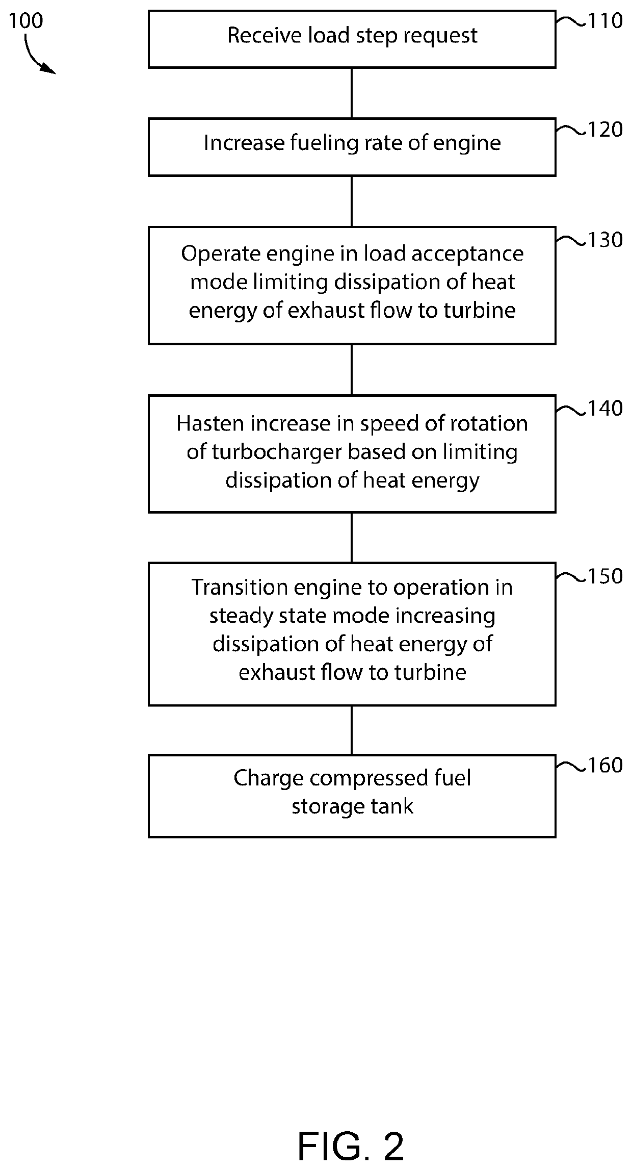
[0004]In one aspect, a method of operating an engine system includes feeding a flow of exhaust from combustion cylinders in an engine to a turbine coupled to a compressor in a turbocharger, and increasing a fueling rate of the engine based on a load step request. The method further includes increasing a speed of rotation of the turbocharger based on the increasing of the fueling rate, and limiting dissipation of heat energy from the flow of exhaust to the turbine to hasten the increase in the speed of rotation of the turbocharger. The method further includes increasing dissipation of heat energy from the flow of exhaust to the turbine after satisfaction of the load step request.
[0005]In another aspect, an engine system includes an engine having a plurality of combustion cylinders formed therein, and a turbocharger including a turbine and a compressor. The engine system further includes an intake system having an intake conduit extending between an air inlet and the compressor, and between the compressor and the plurality of combustion cylinders. The engine system further includes an exhaust system having an exhaust conduit extending between the plurality of combustion cylinders and the turbine, and a fuel system. The fuel system includes a first fuel admission valve coupled with the intake conduit at an upstream delivery location, and a second fuel admission valve coupled with the intake conduit at a downstream delivery location. The engine system further includes an insulator forming a heat exchange cavity in heat transference contact with the exhaust conduit between the plurality of combustion cylinders and the turbine, and a pump structured to feed a heat exchange fluid into the heat exchange cavity to displace an insulating fluid, for varying heat dissipation of a flow of exhaust from the engine to the turbine.
[0006]In still another aspect, a method of accepting a load step in an engine includes receiving a load step request, and increasing a fueling rate of the engine based on the load step request. The method further includes boosting a pressure of intake air supplied to the engine with a compressor in a turbocharger based on the increasing of the fueling rate. The method further includes operating the engine in a load step acceptance mode at least in part by limiting dissipation of heat energy of a flow of exhaust to a turbine of the turbocharger during the boosting of the pressure of intake air, and transitioning the engine to a steady state mode after satisfaction of the load step request at least in part by increasing dissipation of heat energy from the flow of exhaust to prevent overheating of the turbine.

Problems solved by technology

When changes in engine speed and load are required, such as to accept an increased output requirement of driven equipment, the engine can operate less efficiently or with increased amounts of certain emissions.
Moreover, in many instances an engine will initially decrease its speed relatively sharply when an additional load is demanded, potentially leading to operating stability problems, undue delay in accepting the increased engine load, or requiring engine shut down altogether.

Method used


Image

  • Engine operating method and engine system for improved load step acceptance
  • Engine operating method and engine system for improved load step acceptance

Examples


Embodiment Construction

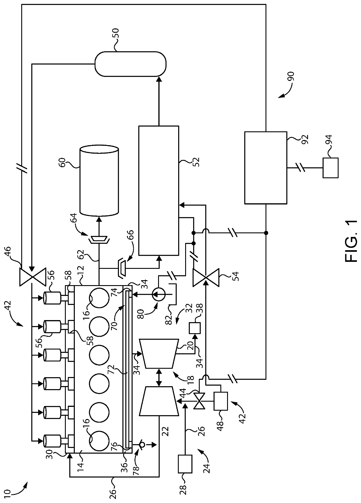
[0009]Referring to FIG. 1, there is shown an internal combustion engine system 10 according to one embodiment. Engine system 10 includes an engine 12 having an engine housing 14 with a plurality of combustion cylinders 16 formed therein. Engine 12 may have any number of cylinders in any suitable arrangement such as a V-pattern, an inline pattern, or still another. Engine system 10 further includes a turbocharger 18 having a turbine 20 and a compressor 22, an intake system 24, and an exhaust system 32. Intake system 24 includes an intake conduit 26 extending between an air inlet 28 and compressor 22, and between compressor 22 and the plurality of combustion cylinders 16. An intake manifold 30 of intake system 24 distributes air for combustion to each of combustion cylinders 16. Exhaust system 32 includes an exhaust conduit 34 extending between the plurality of combustion cylinders 16 and turbine 20, and between turbine 20 and an exhaust outlet 38. Aftertreatment equipment (not shown)...


PUM


Abstract

Operating an engine system includes feeding a flow of exhaust to a turbine in a turbocharger, receiving a load step request, and increasing a speed of rotation of the turbocharger based on an increase in a fueling rate initiated in response to the load step request. Operating the engine system further includes limiting dissipation of heat energy of the flow of exhaust to the turbine to hasten an increase in the speed of rotation of the turbocharger, and increasing dissipation of heat energy from the flow of exhaust after satisfaction of the load step request. Varying of the dissipation of heat energy can be achieved by displacing an insulating fluid in the exhaust manifold with a heat exchange fluid such as water and / or engine coolant.

Description

TECHNICAL FIELD[0001]The present disclosure relates generally to operating an engine system to accept a load step request, and more particularly to hastening an increase in a speed of rotation of a turbocharger during accepting the load step request.BACKGROUND[0002]Internal combustion engines are increasingly called upon to accommodate heightened demands with respect to emissions and efficiency. In the case of certain engine systems emissions and efficiency can be relatively tightly controlled where the engine is operated at a steady state condition with little or no change in engine speed or engine load. When changes in engine speed and load are required, such as to accept an increased output requirement of driven equipment, the engine can operate less efficiently or with increased amounts of certain emissions. Moreover, in many instances an engine will initially decrease its speed relatively sharply when an additional load is demanded, potentially leading to operating stability pr...

Claims


Application Information

Patent Timeline
Patent Type & Authority Patents(United States)
IPC IPC(8): F02B37/20F02D41/32F01N13/10F02M35/10F01P5/10F02M21/02F02D41/00F01N3/04F02B37/02F01P3/20
CPCF02B37/20F01N3/046F01N13/102F01P3/20F01P5/10F02B37/02F02D41/0027F02D41/32F02M21/0221F02M21/0245F02M21/0278F02M35/10157F02M35/10216F01P2060/16F02D41/10F02D41/0007F02D19/024F01P3/02F01P2003/021F01P2003/022Y02T10/12Y02T10/30
Inventor WANG, PAUL SAI KEATSINGH, JASWINDERGINTER, DAVID
Owner CATERPILLAR INC
Learn More