AI technical title is built by Patsnap AI team. It summarizes the technical point description of the patent document.
a technology of haptic rings and ring rings, which is applied in the field of haptic rings, can solve the problems of complex devices that require frequent maintenance, entail a high degree of constructive complexity in pneumatic circuits and relative power supply, and compact and small in size, and achieve the effect of greater flexibility and adaptability
Active Publication Date: 2022-03-29
WEART SRL
View PDF19 Cites 0 Cited by
Summary
Abstract
Description
Claims
Application Information
AI Technical Summary
This helps you quickly interpret patents by identifying the three key elements:
Problems solved by technology
Method used
Benefits of technology
Benefits of technology
The present invention provides a device that can stimulate a user's body part with haptic sensations. The device is designed to be more flexible and adaptable to different usage conditions compared to previous devices, making it easier to provide effective haptic sensations to users.
Problems solved by technology
However, such a device, although compact and small in size, requires a hydraulic circuit to supply the pneumatic element.
Furthermore, such a complex device requires frequent maintenance aimed at avoiding the risk of breakage by allowing the fluid, inside the pneumatic circuit, to enter correctly and rapidly into the inflation chamber of the pneumatic element.
Moreover, for a correct operation of the thermal module and of the vibration module, the presence of an electrical circuit is required which, in addition to the pneumatic circuit, weighs down the overall device structure and entails problems of overall size and possibility of wearing it.
Moreover, since this device can be fixed by means of a strap to a body part of the user, it is subject to an unsafe assembly, thus reducing its reliability.
However, even here the ring is fixed by means of a strap to a part of the user's body, resulting in a poor stability.
Moreover, flexibility of the strap makes the entire ring yielding, reducing the precision and speed of transmission of tactile stimuli.
Finally, the device does not lend itself easily to applying further stimuli, such as for example thermal or vibrational stimuli.
Method used
Image
Click on the blue label to locate the original text in one second.
Reading with bidirectional positioning of images and text.
Examples
second embodiment
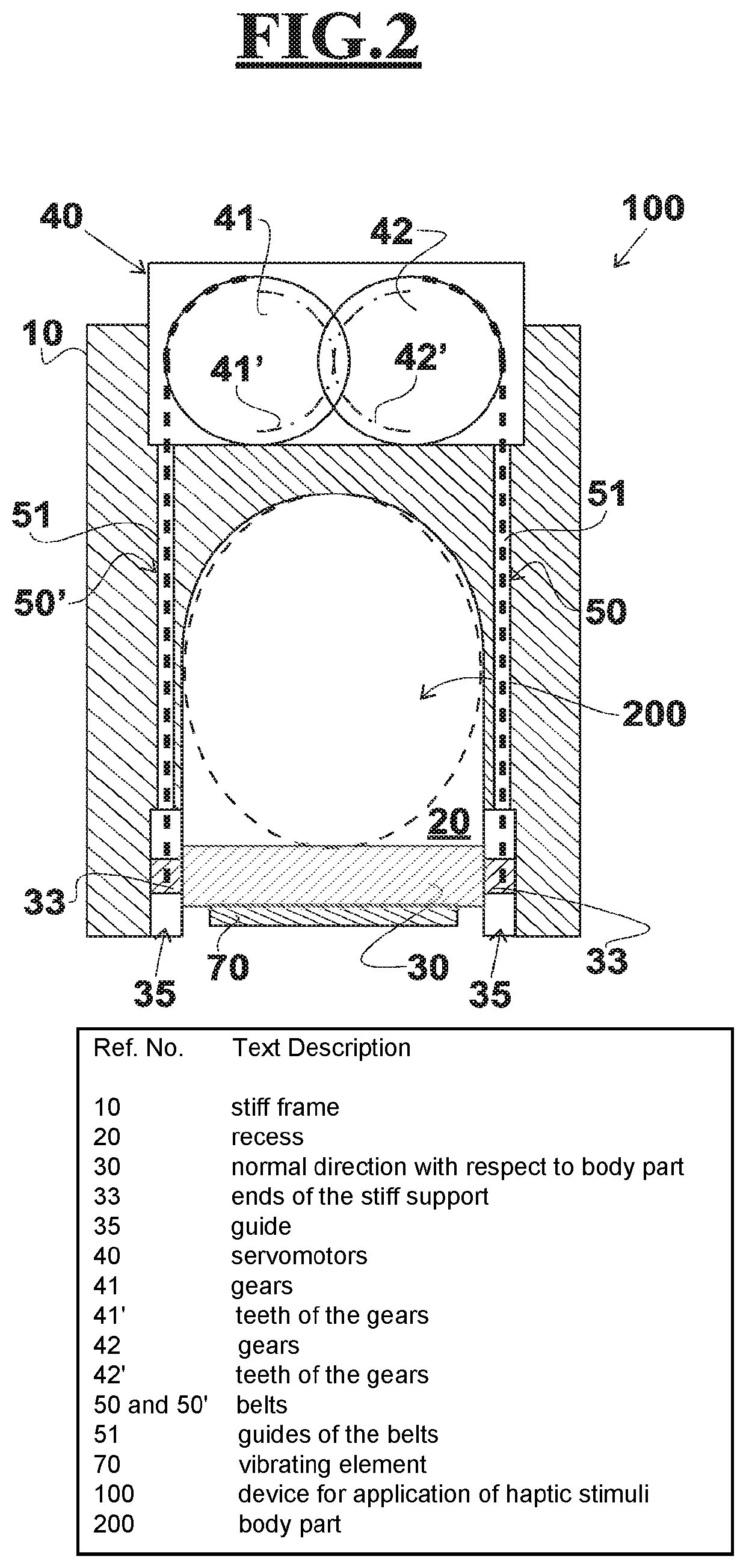
[0064]With reference to FIG. 2, the invention is shown, similar to that of FIG. 1, in which a vibrating element 70 is associated with the stiff support 30.
[0065]In this way, the presence of a vibrating element 70, in contact with the stiff support 30, allows vibratory stimuli of various frequencies to be transferred to the body part 200. The possibility of providing vibration stimuli can be useful if the user is required to perceive a different “texture” of virtual surfaces.
[0066]For example, the vibrating element 70 can be a voice coil supplied with excitation current at frequency values similar to sound signals, or it can be an eccentric mass element or a piezoelectric actuator, or another type.
third embodiment
[0067]With reference to FIG. 3, the invention is shown, similar to that described in FIG. 2, in which the stiff support 30 is in contact, by means of a first face 31, with a second face 62 of a heating / cooling element, for example a Peltier cell 60.
[0068]The presence of a Peltier cell 60, or of another heating / cooling element, allows to have a thermal module which, in contact with the part of the user body 200 through a first face 61 thereof, can expand the range of stimuli that can be generated and can make thermal illusions possible.
[0069]It is also possible that the face 61 of the Peltier cell 60 comprises sectors whose temperature is controlled independently.
[0070]It is therefore possible, for example, to adjust the temperature of the Peltier cell 60 so as to perceive thermal variations in the body part 200 following the interaction with thermally altered virtual environments.
[0071]The Peltier cell 60 can comprise a thermistor, not shown in the figure, so as to limit the inrush ...
PUM
Abstract
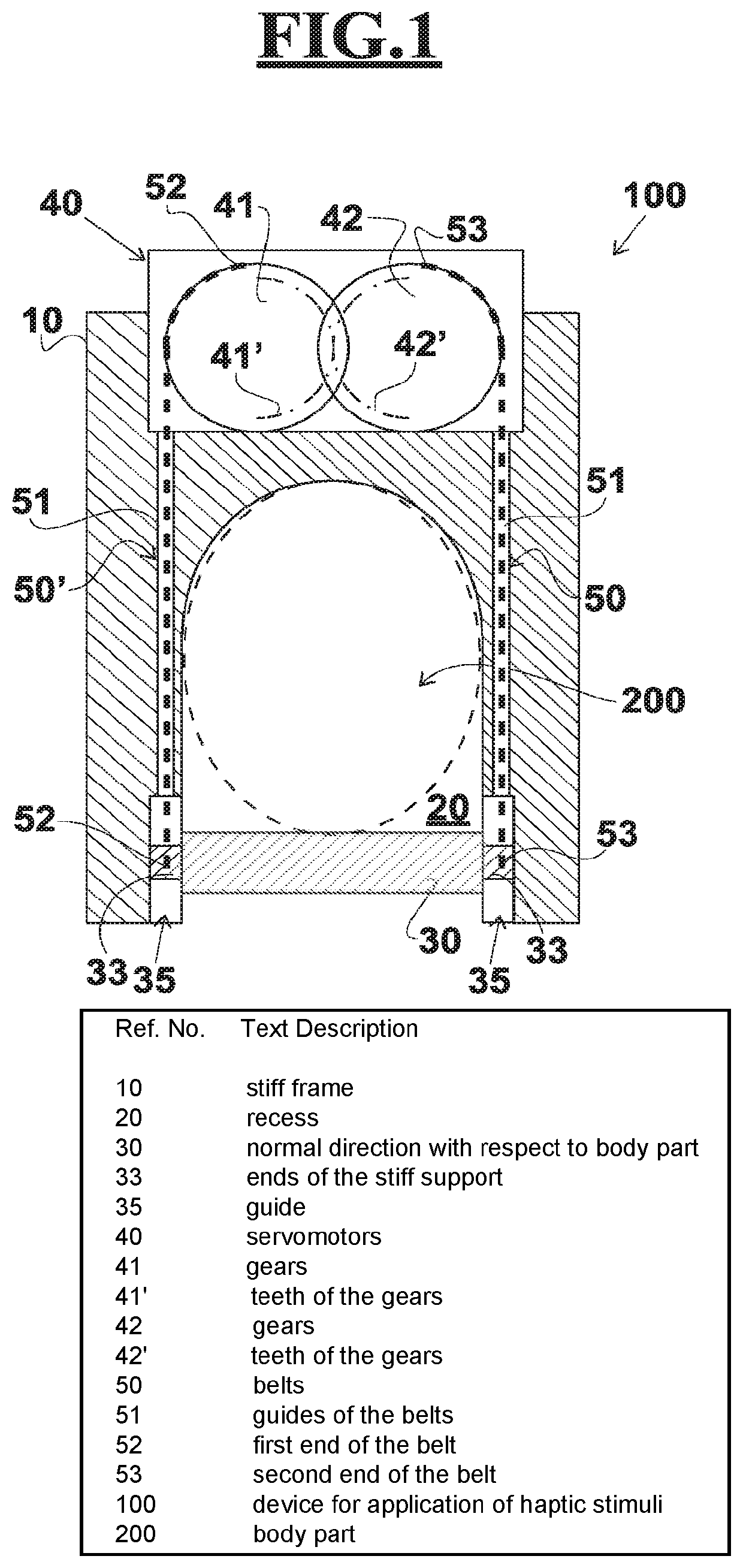
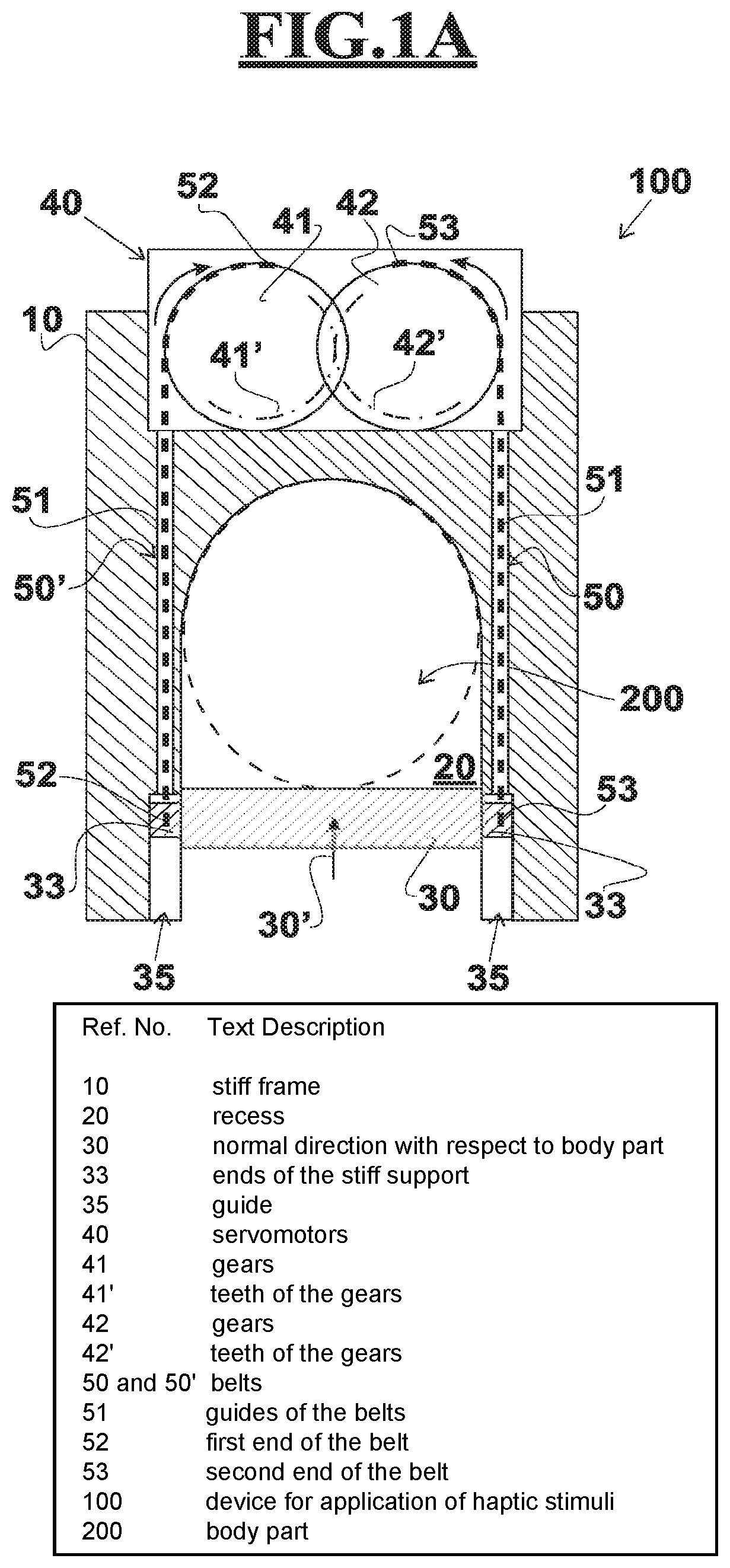
Device (100) for applying haptic stimuli to a body part (200) of a user, comprising a stiff support (30) configured to contact the body part 200; a containing element configured to keep the body part (200) in contact with the stiff support (30); an actuating element configured to push the stiff support (30) into the containing element and apply a pressure to the body part 200. The containing element comprises a stiff frame (10) defining a recess (20) to house the body part 200. The frame (10) comprises two lateral stiff guides (51) defining the recess (20) and the stiff support (30) is configured to move in a guided manner in the stiff guides (51). At least one servomotor (40, 40′) is provided connected integrally to the stiff frame (10) on the opposite side to the stiff support (30) with respect to the recess (20) and arranged to cause a relative movement, inside the recess (20) and with respect to the lateral stiff rails (51), of the stiff support (30) with respect to the body part (200). At least one belt (50, 50′) sliding parallel to the lateral stiff rails (51) and connected respectively with the servomotor (40) and the stiff support (30) is provided. The servomotor (40) is configured to operate the or each belt (50, 50′) to cause guided movement in the stiff guides (51) of the stiff support (30).
Description
SCOPE OF THE INVENTION[0001]The present invention relates to an annular-shaped sensory stimulation device adapted to be worn by a patient for use in various fields, such as for example the field of virtual reality, the field of rehabilitation, and others.DESCRIPTION OF THE PRIOR ART[0002]Numerous devices capable of providing haptic stimuli to users, i.e. capable of inducing haptic perceptions, are known today. In particular, devices capable of providing haptic stimuli such as to communicate in a unique or combined manner information on temperature, pressure and roughness of a surface are known.[0003]These devices are generally used in various sectors. For example, it is possible to use them in virtual environments to encourage the perceptive immersion of a user in it. These can be used in the medical field, for example where a surgeon has to drive a robot by remote control to perform remote surgical operations. In this case, the surgeon is able to perceive the interaction forces bet...
Claims
Application Information
Patent Timeline
Application Date:The date an application was filed.
Publication Date:The date a patent or application was officially published.
First Publication Date:The earliest publication date of a patent with the same application number.
Issue Date:Publication date of the patent grant document.
PCT Entry Date:The Entry date of PCT National Phase.
Estimated Expiry Date:The statutory expiry date of a patent right according to the Patent Law, and it is the longest term of protection that the patent right can achieve without the termination of the patent right due to other reasons(Term extension factor has been taken into account ).
Invalid Date:Actual expiry date is based on effective date or publication date of legal transaction data of invalid patent.

