
Two-Stage Centrifugal Pump

Inactive Publication Date: 2017-01-12
WEIR GABBIONETA SRL
View PDF4 Cites 12 Cited by
  • Summary
  • Abstract
  • Description
  • Claims
  • Application Information

AI Technical Summary

Benefits of technology

The invention described in this patent allows the pump to have greater flexibility and adaptability for different applications and fields. It can meet the requirements of suction and delivery with ease and can be customized to the needs of the user. The design also reduces the number of parts and simplifies assembly and manufacturing. Overall, this pump design provides increased flexibility and customization options while also minimizing the complexity of the pump.

Problems solved by technology

A wrong choice of the type of blades can entail a drastic reduction in the performance of the pump due to known cavitation phenomena.
The fact that the impellers are mounted in series on the same rotation shaft determines a considerable increase in the bulk sizes, at least in the direction of the length of the shaft, which may conflict with possible application requirements.
Because the impellers have the same rotation speed, in some applications this imposes a limit on the performance, that is, on the conditions of pressure or the speed of the fluid that are to be obtained for delivery to the machine.
Due to this condition, the performance of the pump is greatly limited, and also because of restrictive suction conditions which are present in the suction pipe of the pump and which are usually characterized by low NPSHA values (Net Positive Suction Head Available), observance of which is required so that no problems of cavitation can occur in the operation of the pump.
However, such pumps have only been suitable for use in a narrow range of operating conditions.

Method used


Image

  • Two-Stage Centrifugal Pump
  • Two-Stage Centrifugal Pump
  • Two-Stage Centrifugal Pump

Examples


Embodiment Construction

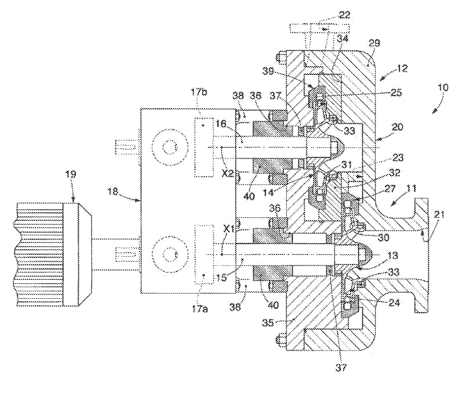
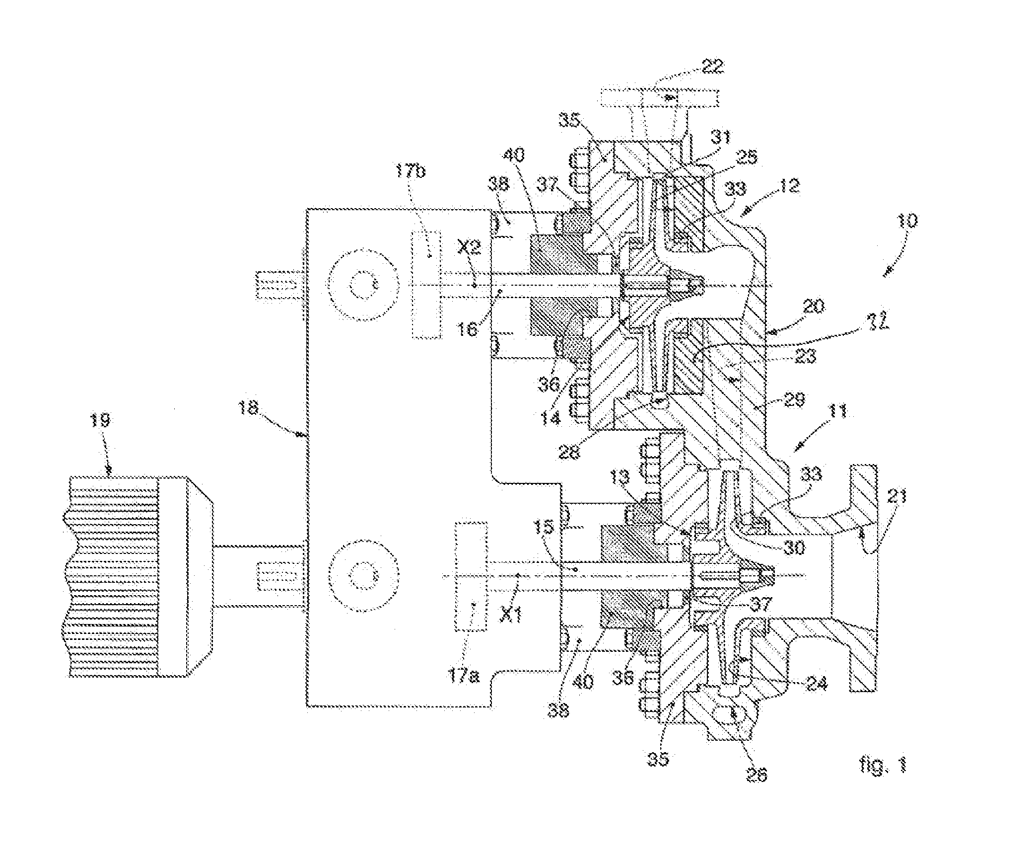
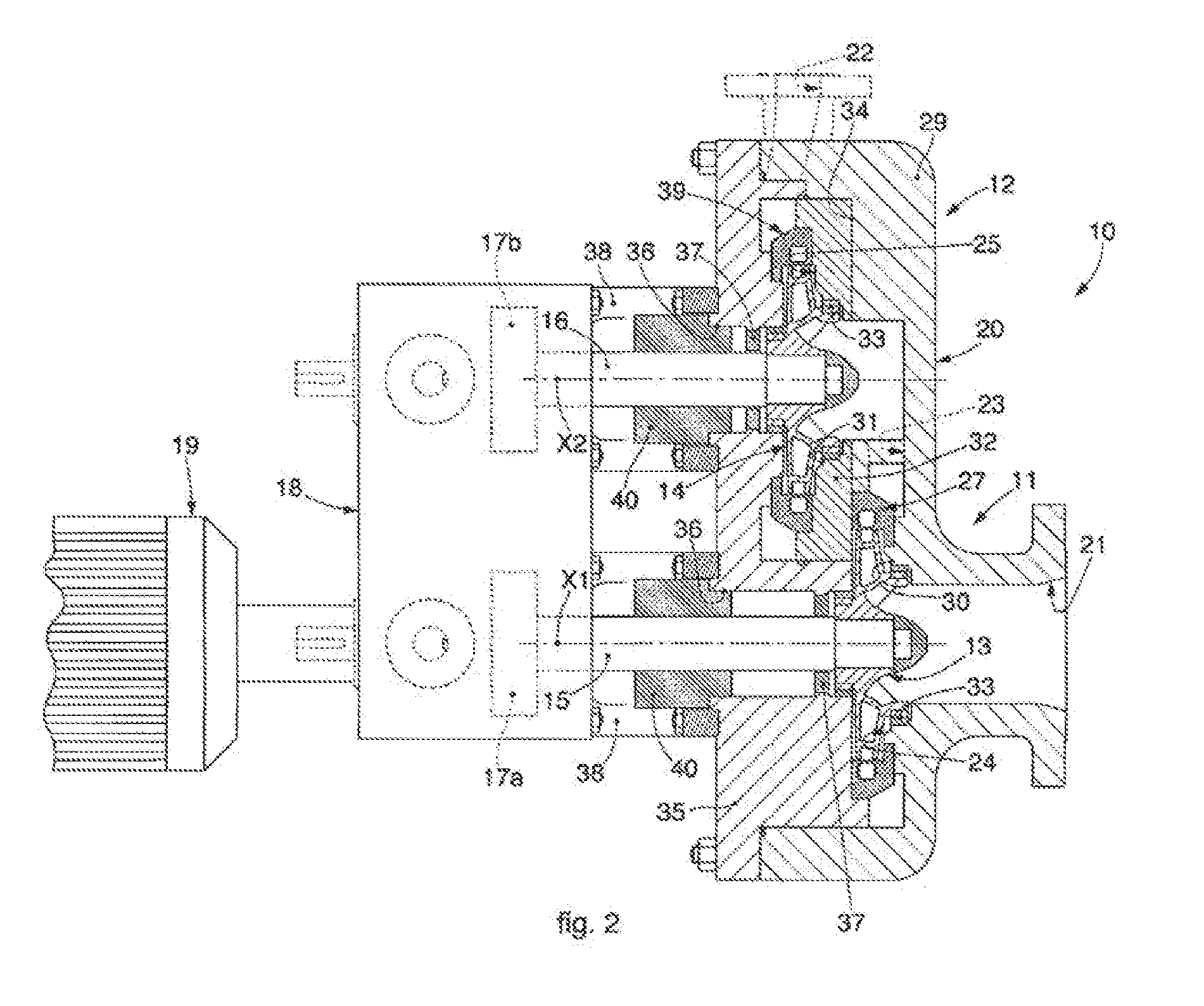
[0059]With reference to FIGS. 1, 2 and 3, a two-stage centrifugal pump is indicated in its entirety by the reference number 10. In each Figure, the same reference numerals have been used to denote like components.

[0060]The pump 10 comprises a first stage 11 and a second stage 12 which is hydraulically connected to the first stage 11—that is, the second stage 12 is configured to receive the fluid processed by the first stage 11, and to further increase the energy thereof, both in terms of pressure and in terms of speed (velocity).

[0061]The first stage 11 and the second stage 12 respectively comprise a first impeller 13 and a second impeller 14. The first impeller 13 and the second impeller 14 are each provided with a respective array of blades. The first impeller 13 and the second impeller 14 are mounted respectively on a first shaft 15 and on a second shaft 16, distinct from each other. The first shaft 15 and the second shaft 16 have respective axes of rotation X1 and respectively X...


PUM


Abstract

A two-stage centrifugal pump comprising: a first stage provided with a first impeller mounted on a first shaft and a second stage provided with a second impeller mounted on a second shaft distinct from said first shaft; and hydraulically connected to the first stage, and the stages mounted in a single support body, provided with a first chamber and a second chamber in which said first impeller and respectively said second impeller are contained; said support body comprises a case made in a single body therewith and provided with a first cavity and a second cavity that define respective portions of said first chamber and said second chamber; in at least one of either said first cavity or said second cavity one or more adaptors are mounted, to adapt the geometry of the first chamber and / or the second chamber to the type and size of impeller adopted.

Description

TECHNICAL FIELD[0001]This disclosure relates in general to a two-stage centrifugal pump, that is, comprising at least two impellers provided with respective arrays of blades, each of which is associated with fixed pipes and used for the suction and discharge of a fluid, generally a liquid.BACKGROUND OF THE DISCLOSURE[0002]Centrifugal pumps are configured to exert work on a fluid which translates into pressurized and kinetic energy.[0003]Centrifugal pumps generally have a rotary part, also called impeller, which in use can be caused to rotate around a rotation shaft.[0004]The impeller is provided with a plurality of blades associated with a hub and defining between them mobile pipes in which the fluid flows with a continuous motion.[0005]The impeller is closed inside a case in which the fixed pipes are made for the inlet and outlet of the fluid from the impeller.[0006]The case comprises a suction pipe to feed the fluid to the impeller and an outlet pipe to discharge the fluid from th...

Claims


Application Information

Patent Timeline
IPC IPC(8): F04D13/14F04D29/42F04D29/22F04D1/06F04D13/02
CPCF04D13/14F04D1/06F04D29/426F04D29/22F04D13/021F04D13/06F04D29/628
Inventor MARENCO, GIACOMOSACCHI, ILARIOCICERI, RICCARDONICCHIO, ALESSANDRO
Owner WEIR GABBIONETA SRL
Learn More