Supercharge Your Innovation With Domain-Expert AI Agents!

Ceramic shielding apparatus

a shielding apparatus and ceramic technology, applied in the field of ceramic shielding apparatus, can solve the problems of increased manufacturing cost, large volume, and heavy weight, and achieve excellent insulating and shielding properties

Active Publication Date: 2022-03-29
LEE HAN SUNG
View PDF6 Cites 0 Cited by
  • Summary
  • Abstract
  • Description
  • Claims
  • Application Information

AI Technical Summary

Benefits of technology

The ceramic shielding apparatus is designed to be safe for the human body and provide good insulation and protection from various conditions. The shield is made of ceramic shielding blocks and reinforcing members that strengthen the connection between the blocks. This invention aims to improve the ability to protect sensitive components or people from harm.

Problems solved by technology

Meanwhile, in the case of tanks to which lead for radiation shielding is applied, there are disadvantages that the volume is very large and the weight is very heavy due to the material properties of lead.
In addition, shielding parts that are irrelevant to the generation of X-rays are required due to application of a shielding tank to which lead is applied, which causes problems such as increased manufacturing costs.

Method used


Image

  • Ceramic shielding apparatus
  • Ceramic shielding apparatus
  • Ceramic shielding apparatus

Examples


first embodiment

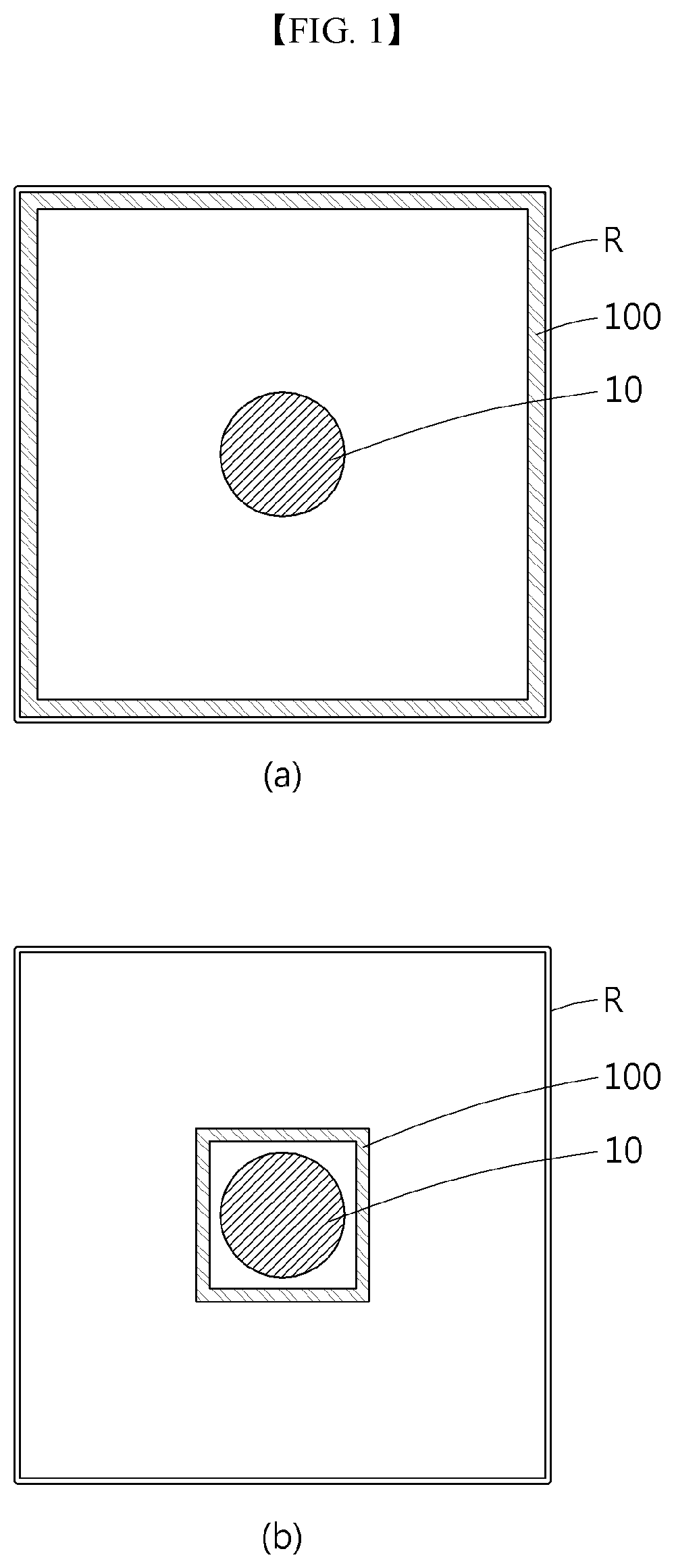
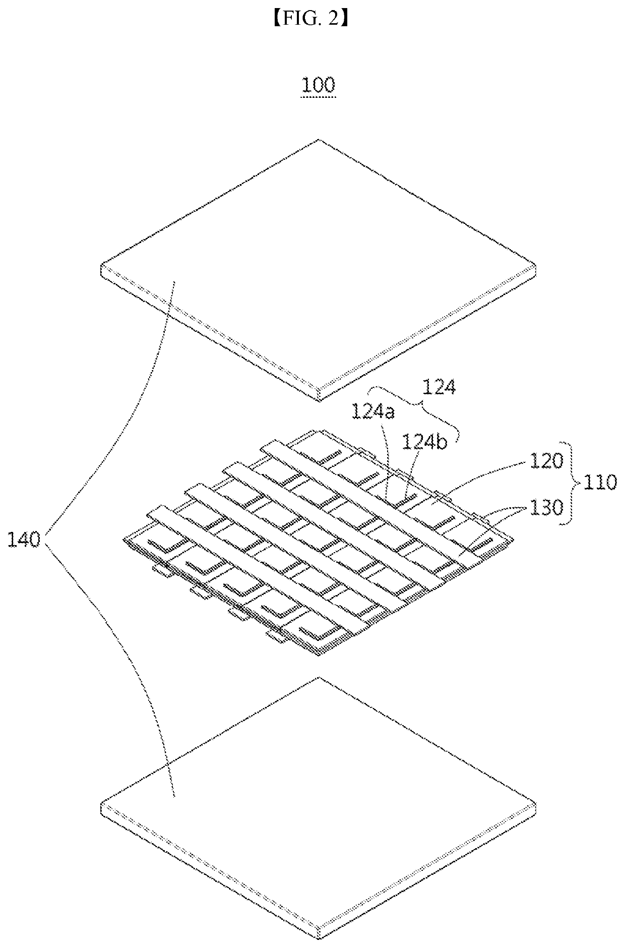
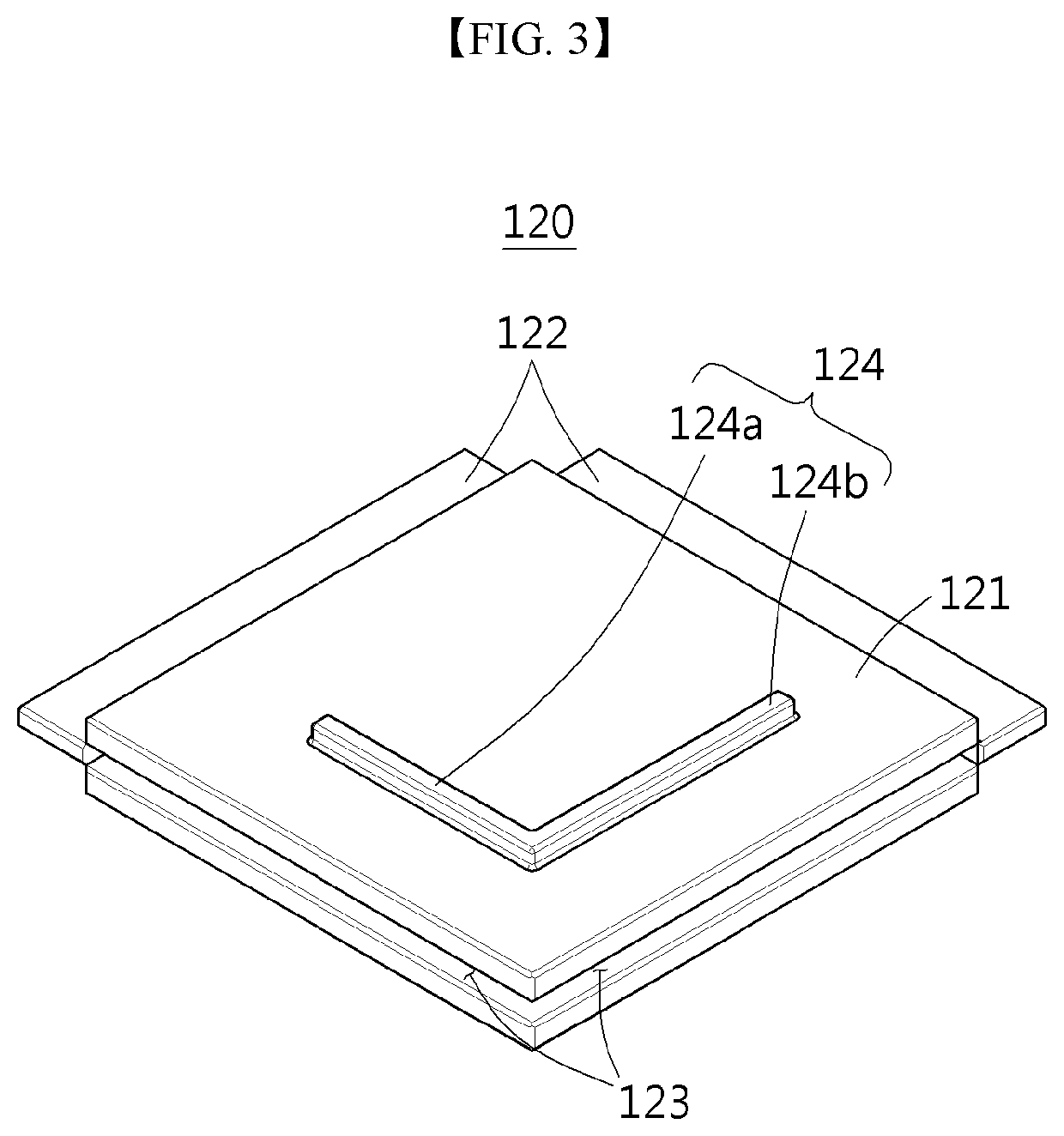
[0039]Referring to FIGS. 1 and 2, a ceramic shielding apparatus 100 according to a preferred first embodiment of the present disclosure includes a shield 110 and supports 140.

[0040]For reference, the ceramic shielding apparatus 100 described in the first embodiment is installed in a shielding room R for separating an X-ray tube 10 from the outside and is provided outside of the X-ray tube 10 as shown in (a) and (b) of FIG. 1. Here, the ceramic shielding apparatus 100 may be installed to be in close contact with inner walls of the shielding room R as shown in (a) of FIG. 1, or may be installed to be spaced from inner walls of the shielding room R and to surround the X-ray tube 10 in a position adjacent to the X-ray tube 10 as shown in (b) of FIG. 1. An installation position of the ceramic shielding apparatus 100 is not limited to those illustrated in FIG. 1 and may be installed at various position outside of the X-ray tube 10 so long as radiation generated from the X-ray tube 10 can ...

second embodiment

[0058]For reference, the X-ray tube 10 illustrated in the second embodiment includes an X-ray source 20 configured to generate electrons for X-ray generation, an anode 30 configured to generate X-rays when struck by electrons generated from the X-ray source 20, and an X-ray body 40 configured to support the X-ray source 20 and the anode 30.

[0059]Here, the X-ray source 20 may be isolated and supported by partition walls 21, and an insulating material is filled between the partition walls 21 to electrically protect the X-ray source 20. In addition, the anode 30 is provided with an inclined target 31 so that generated X-rays are reflected by the target 31 of the main body 40 and guided to the outside. Since such a configuration of the reflective X-ray tube 10 is not the gist of the present disclosure, detailed description and illustration thereof are omitted.

[0060]A first shield 210 is provided inside the X-ray tube 10 and is provided as a bottom surface, i.e., a base, of the X-ray tub...

third embodiment

[0067]FIG. 7 schematically illustrates a ceramic shielding apparatus 300 according to a preferred third embodiment of the present disclosure.

[0068]Referring to FIG. 7, the ceramic shielding apparatus 300 according to the third embodiment is also provided inside an X-ray tube 10 to shield radiation.

[0069]Here, the X-ray tube 10 according to the third embodiment is a transmission type different from the reflective X-ray tube 10 according to the second embodiment illustrated in FIG. 6. The transmission-type X-ray tube 10 shown in FIG. 7 is provided with an anode 30 including a target 31 that faces an X-ray source 20, thereby emitting X-rays to the outside through the target 31. The X-ray source 20 is supported by a main body 40.

[0070]The ceramic shielding apparatus 300 according to the third embodiment includes first and second shields 310 and 320. Here, both the first and second shields 310 and 320 extend vertically upward from the main body 40 that supports the X-ray source 20, and a...


PUM

PropertyMeasurementUnit
thicknessaaaaaaaaaa
thicknessaaaaaaaaaa
thicknessaaaaaaaaaa

Abstract

Disclosed is a ceramic shielding apparatus including at least one shield made of a ceramic material and provided inside or outside an X-ray tube to shield radiation; and supports configured to support the shield. According to such a configuration, disadvantages of conventional shielding materials such as lead can be addressed, so that a shield apparatus having excellent shielding properties while being harmless to the human body can be provided.

Description

CROSS-REFERENCE TO RELATED APPLICATION[0001]This application claims priority to Korean Patent Application No. 10-2019-0089615, filed on Jul. 24, 2019 in the Korean Intellectual Property Office, the disclosure of which is incorporated herein by reference.BACKGROUND OF THE DISCLOSUREField of the Disclosure[0002]The present disclosure relates to a ceramic shielding apparatus, and more particularly, to a ceramic shielding apparatus that is harmless to the human body and exhibits excellent insulating and shielding properties under various conditions.Description of the Related Art[0003]An X-ray apparatus, which is an apparatus for generating X-rays, consists of an X-ray tube composed of a cathode and anode in a vacuum tube, a high-voltage control for applying high voltage to the X-ray tube, and a cooling device for cooling heat generated in the X-ray tube.[0004]In the case of general X-ray tubes, an insulating oil is configured to have cooling and insulating properties. Accordingly, a met...

Claims


Application Information

Patent Timeline
Patent Type & Authority Patents(United States)
IPC IPC(8): H01J37/18H01J35/16H01J35/12G21F3/00G21F7/00G21F1/06H01J35/18H01J35/08
CPCH01J35/18G21F3/00G21F7/00H01J35/112H01J35/12H01J35/165G21F1/06H01J2235/166H01J35/16A61B6/107A61B6/40A61B6/4488G21F3/04
Inventor LEE, HAN SUNG
Owner LEE HAN SUNG
Features
  • R&D
  • Intellectual Property
  • Life Sciences
  • Materials
  • Tech Scout
  • Unparalleled Data Quality
  • Higher Quality Content
  • 60% Fewer Hallucinations
Learn More