Ceramic shielding apparatus
a shielding apparatus and ceramic technology, applied in the field of ceramic shielding apparatus, can solve the problems of increased manufacturing cost, large volume, and heavy weight, and achieve excellent insulating and shielding properties
- Summary
- Abstract
- Description
- Claims
- Application Information
AI Technical Summary
Benefits of technology
Problems solved by technology
Method used
Image
Examples
first embodiment
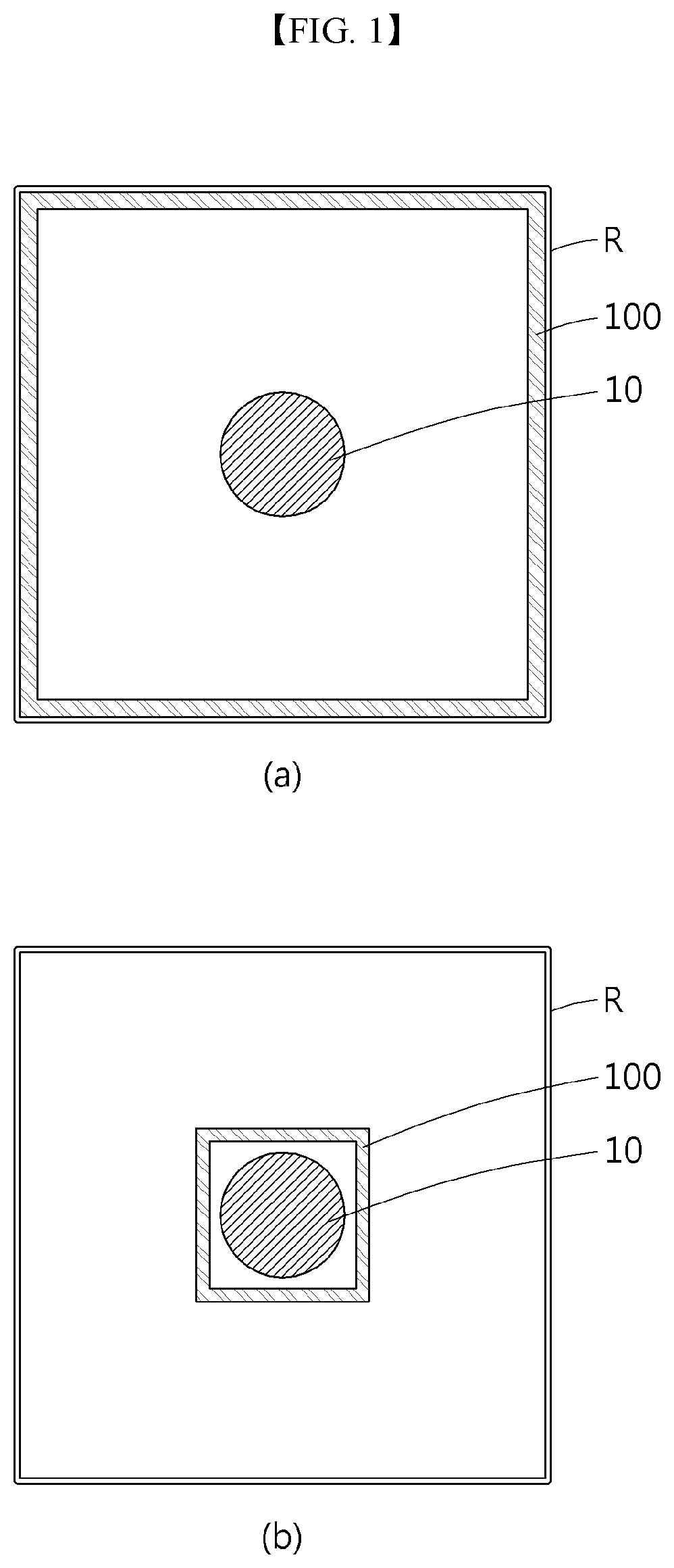
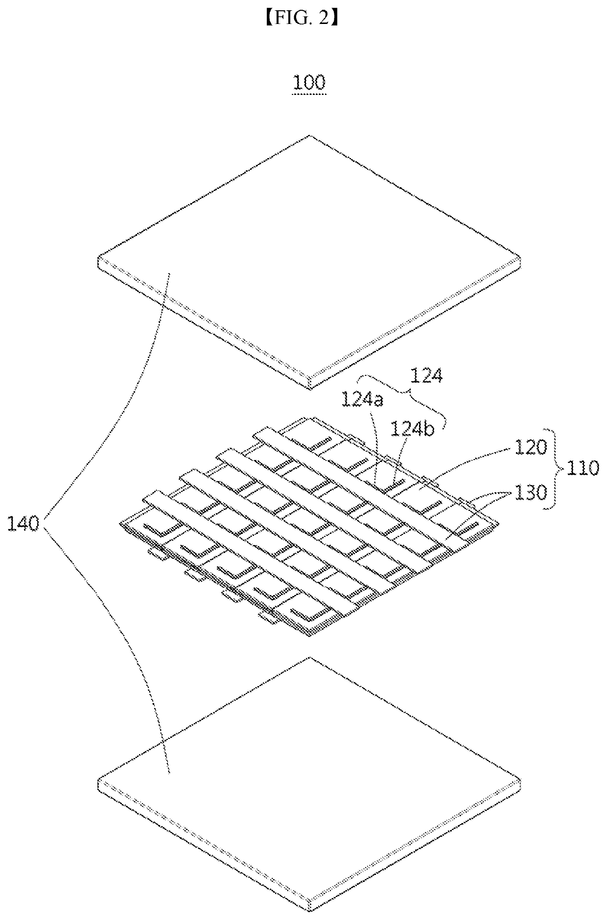
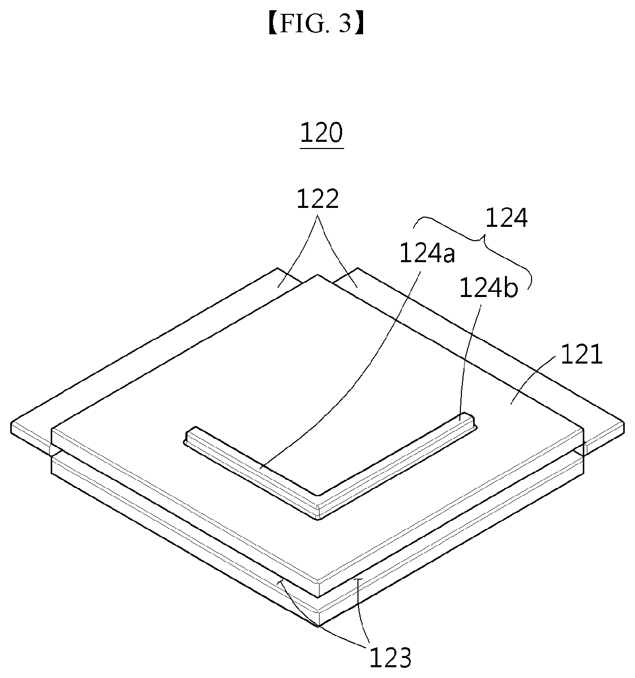
[0039]Referring to FIGS. 1 and 2, a ceramic shielding apparatus 100 according to a preferred first embodiment of the present disclosure includes a shield 110 and supports 140.
[0040]For reference, the ceramic shielding apparatus 100 described in the first embodiment is installed in a shielding room R for separating an X-ray tube 10 from the outside and is provided outside of the X-ray tube 10 as shown in (a) and (b) of FIG. 1. Here, the ceramic shielding apparatus 100 may be installed to be in close contact with inner walls of the shielding room R as shown in (a) of FIG. 1, or may be installed to be spaced from inner walls of the shielding room R and to surround the X-ray tube 10 in a position adjacent to the X-ray tube 10 as shown in (b) of FIG. 1. An installation position of the ceramic shielding apparatus 100 is not limited to those illustrated in FIG. 1 and may be installed at various position outside of the X-ray tube 10 so long as radiation generated from the X-ray tube 10 can ...
second embodiment
[0058]For reference, the X-ray tube 10 illustrated in the second embodiment includes an X-ray source 20 configured to generate electrons for X-ray generation, an anode 30 configured to generate X-rays when struck by electrons generated from the X-ray source 20, and an X-ray body 40 configured to support the X-ray source 20 and the anode 30.
[0059]Here, the X-ray source 20 may be isolated and supported by partition walls 21, and an insulating material is filled between the partition walls 21 to electrically protect the X-ray source 20. In addition, the anode 30 is provided with an inclined target 31 so that generated X-rays are reflected by the target 31 of the main body 40 and guided to the outside. Since such a configuration of the reflective X-ray tube 10 is not the gist of the present disclosure, detailed description and illustration thereof are omitted.
[0060]A first shield 210 is provided inside the X-ray tube 10 and is provided as a bottom surface, i.e., a base, of the X-ray tub...
third embodiment
[0067]FIG. 7 schematically illustrates a ceramic shielding apparatus 300 according to a preferred third embodiment of the present disclosure.
[0068]Referring to FIG. 7, the ceramic shielding apparatus 300 according to the third embodiment is also provided inside an X-ray tube 10 to shield radiation.
[0069]Here, the X-ray tube 10 according to the third embodiment is a transmission type different from the reflective X-ray tube 10 according to the second embodiment illustrated in FIG. 6. The transmission-type X-ray tube 10 shown in FIG. 7 is provided with an anode 30 including a target 31 that faces an X-ray source 20, thereby emitting X-rays to the outside through the target 31. The X-ray source 20 is supported by a main body 40.
[0070]The ceramic shielding apparatus 300 according to the third embodiment includes first and second shields 310 and 320. Here, both the first and second shields 310 and 320 extend vertically upward from the main body 40 that supports the X-ray source 20, and a...
PUM
| Property | Measurement | Unit |
|---|---|---|
| thickness | aaaaa | aaaaa |
| thickness | aaaaa | aaaaa |
| thickness | aaaaa | aaaaa |
Abstract
Description
Claims
Application Information
 - R&D
- Intellectual Property
- Life Sciences
- Materials
- Tech Scout
- Unparalleled Data Quality
- Higher Quality Content
- 60% Fewer Hallucinations
Browse by: Latest US Patents, China's latest patents, Technical Efficacy Thesaurus, Application Domain, Technology Topic, Popular Technical Reports.
© 2025 PatSnap. All rights reserved.Legal|Privacy policy|Modern Slavery Act Transparency Statement|Sitemap|About US| Contact US: help@patsnap.com


