Blank for forming a container

a container and blank technology, applied in the field of blank, can solve the problem of unsuitable application of adhesives, and achieve the effect of bonded more effectively

Active Publication Date: 2022-04-26
JT INT SA
View PDF5 Cites 0 Cited by
  • Summary
  • Abstract
  • Description
  • Claims
  • Application Information

AI Technical Summary

Benefits of technology

[0008]An object of the present invention is to provide a blank with surfaces that can be bonded more effectively, without otherwise interfering in the assembly process.
[0010]It has been found that surface tension is an important factor in determining the integrity of a bond. It has also been found that the application of a main substance on the first blank surface may, without counter measures being taken, reduce surface tension in the attachment regions such that it is outside the predetermined range and unsuitable for application of an adhesive. By treating the attachment region it is possible to counteract these undesirable effects and to maintain surface tension in the predetermined range. Thus, treating the attachment region can provide better conditions for an adhesive and decreased risk of detachment, even in high speed manufacturing processes. The surface tension of the attachment region before the application of a main substance and after treatment do not need to be the same; both surface tensions, before and after, need to be comprised within a predetermined range, suitable for application of an adhesive, but their values can differ.
[0013]The main substance may be selected from the group of an ink, a varnish, a lacquer or a combination thereof and is applied onto the first blank surface, having the attachment region with a surface tension in the predetermined range. The main substance is preferably not applied in the attachment regions. Nevertheless the application process may affect the surface tension in the attachment regions, in the absence of counter measures. It has been found that treatment of the attachment regions can control the surface tension to enable effective bonding at high speeds.
[0018]The step of treating the attachment region of the first blank surface may involve applying an auxiliary substance. The auxiliary substance may be selected from the group of an ink, a varnish, a lacquer or a combination thereof. Typically the attachment region of the first blank surface is unprinted to improve bonding integrity. Surprisingly it has been found that applying an auxiliary substance can improve bonding integrity and maintain a surface tension in the predetermined range following application of the main substance.
[0020]The auxiliary substance may be applied to the attachment region of the first blank surface at the same time as the main substance is applied to the first blank surface. Alternatively the auxiliary substance may be applied before or after application of the main substance. The combined effect of application of the main substance onto the first blank surface and the auxiliary substance onto the attachment region of the first blank surface may result in a surface tension in the attachment region that is within the predetermined range. In one arrangement, the step of applying the main substance onto at least the first blank surface may reduce the surface tension of the attachment region of the first blank surface so that it is outside the predetermined range, and the step of treating the attachment region of the first blank surface may increase the surface tension so that it is within the predetermined range.
[0024]The method may comprise forming a plurality of score lines or perforations in the attachment regions of the at least one printed surface. Score lines have been found previously to improve adhesion by increasing absorption of an adhesive in the attachment region during bonding.

Problems solved by technology

It has also been found that the application of a main substance on the first blank surface may, without counter measures being taken, reduce surface tension in the attachment regions such that it is outside the predetermined range and unsuitable for application of an adhesive.

Method used


Image

  • Blank for forming a container
  • Blank for forming a container
  • Blank for forming a container

Examples


Embodiment Construction

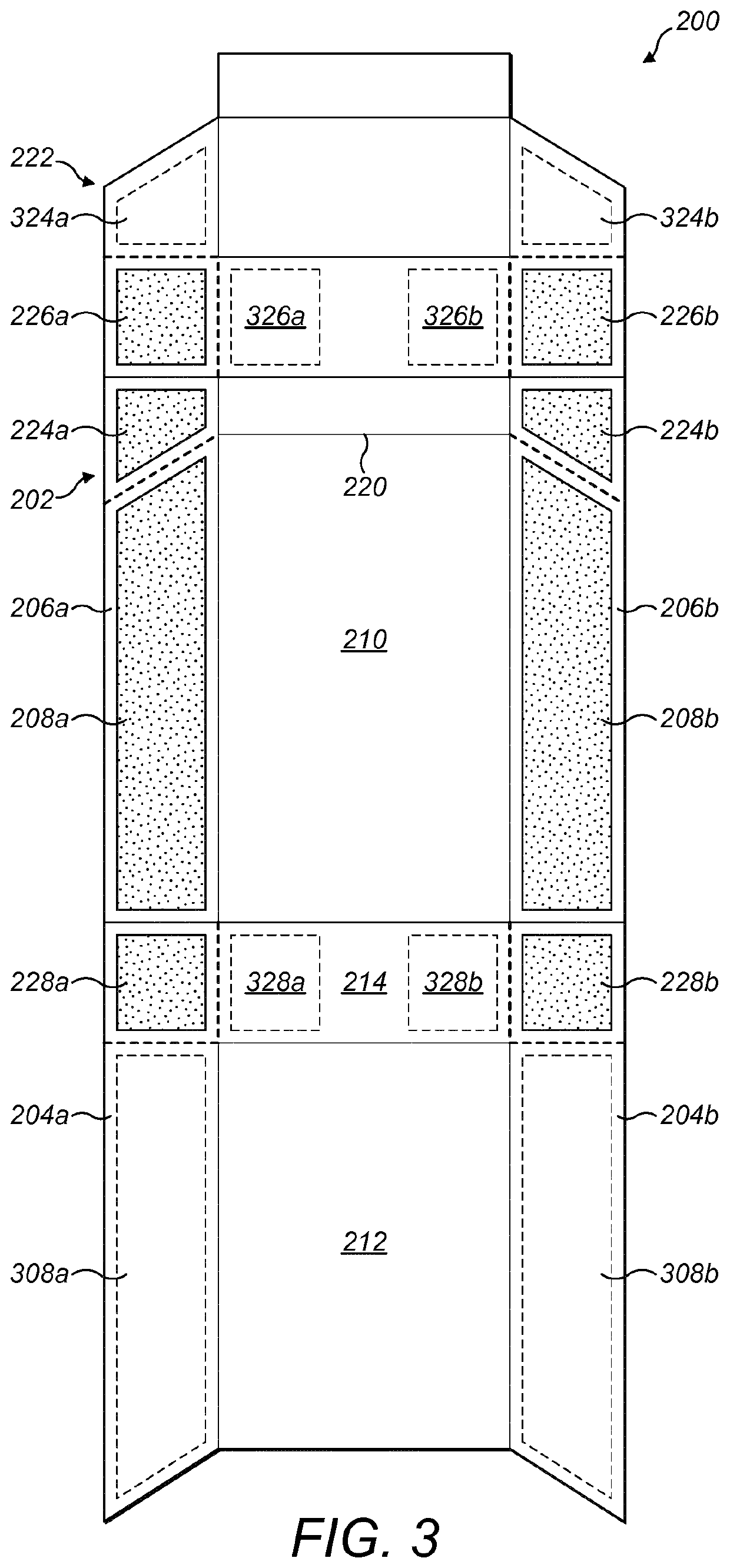
[0038]FIG. 3 is a plan view of an upper surface 202 of a blank 200. The upper surface 202 of the blank is printed in a conventional manner using an ink, varnish, lacquer, or a combination thereof, to create a design and include legally required information, such as health warnings, or manufacturing details. The reverse surface of the blank 200 is unprinted in this embodiment. However, it is possible that the reverse surface could also be printed, at least partially, so that internal surfaces of the container include designs or information.

[0039]The blank 200 includes cut lines (indicated with dotted lines in FIG. 3) and fold lines (indicated with solid lines in FIG. 3). A hinge line 220 is provided between a lid 222 and the remainder of the pack. The upper surface 202 of the blank 200 includes a front panel 210, a back panel 212 and a bottom panel 214. When the blank 200 is folded and formed around a bundle of smoking articles, the front panel 210, back panel 212 and bottom panel 21...


PUM

PropertyMeasurementUnit
surface tensionaaaaaaaaaa
particle sizeaaaaaaaaaa

Abstract

A blank has an upper surface and a reverse surface. The upper surface is printed in a conventional manner and includes outer side panels and inner side panels. Attachment regions are provided on the inner side panels of the outer surface, and corresponding attachment regions are provided on the outer side panels of the reverse surface. During assembly the respective attachment regions are arranged to face one another and an adhesive is provided therebetween. In the present method, the attachment regions of the upper surface initially have a surface tension in the range from around 34 dynes / cm to 60 dynes / cm before the upper surface is printed. The attachment regions are treated in order to maintain a surface tension in the desired range of 34 dynes / cm to 60 dynes / cm, following printing and before any adhesive is applied. This is achieved by applying an auxiliary printing medium to the attachment regions.

Description

CROSS-REFERENCE TO RELATED APPLICATIONS[0001]The present application is a national phase entry under 35 U.S.C. § 371 of International Application No. PCT / EP2017 / 074310, filed Sep. 26, 2017, published in English, which claims priority to European Application No. 16191136.7 filed Sep. 28, 2016, the disclosures of which are incorporated herein by reference.BACKGROUND OF THE INVENTION[0002]The present invention relates to a blank, a container, and respective methods for forming a blank and a container.[0003]Typically, containers for smoking articles are formed from blanks made out of paper or card. In order to form a container the blanks are bent and / or folded around a charge of smoking articles. The blanks are then glued together at dedicated overlap regions so as to form the container. The blanks can be laminated, typically by having a base board made out of paper or card, and a laminate layer made out of aluminium foil or PET foil.[0004]FIG. 1 is a perspective view of a container 2 h...

Claims


Application Information

Patent Timeline
Patent Type & Authority Patents(United States)
IPC IPC(8): B31B50/88B31B50/62B31B50/74B31B110/35B31B100/00B31B120/10B31B110/30
CPCB31B50/624B31B50/74B31B50/745B31B50/88B31B50/742B31B2100/00B31B2100/0028B31B2110/30B31B2110/35B31B2120/102B31B2241/003
Inventor TANAKA, KENTALATUSZEK, DOMINIC LUKASZCLAUSEN, MIKE
Owner JT INT SA
Why Eureka
Try Eureka