Control system and control method
- Summary
- Abstract
- Description
- Claims
- Application Information
AI Technical Summary
Benefits of technology
Problems solved by technology
Method used
Image
Examples
embodiment 1
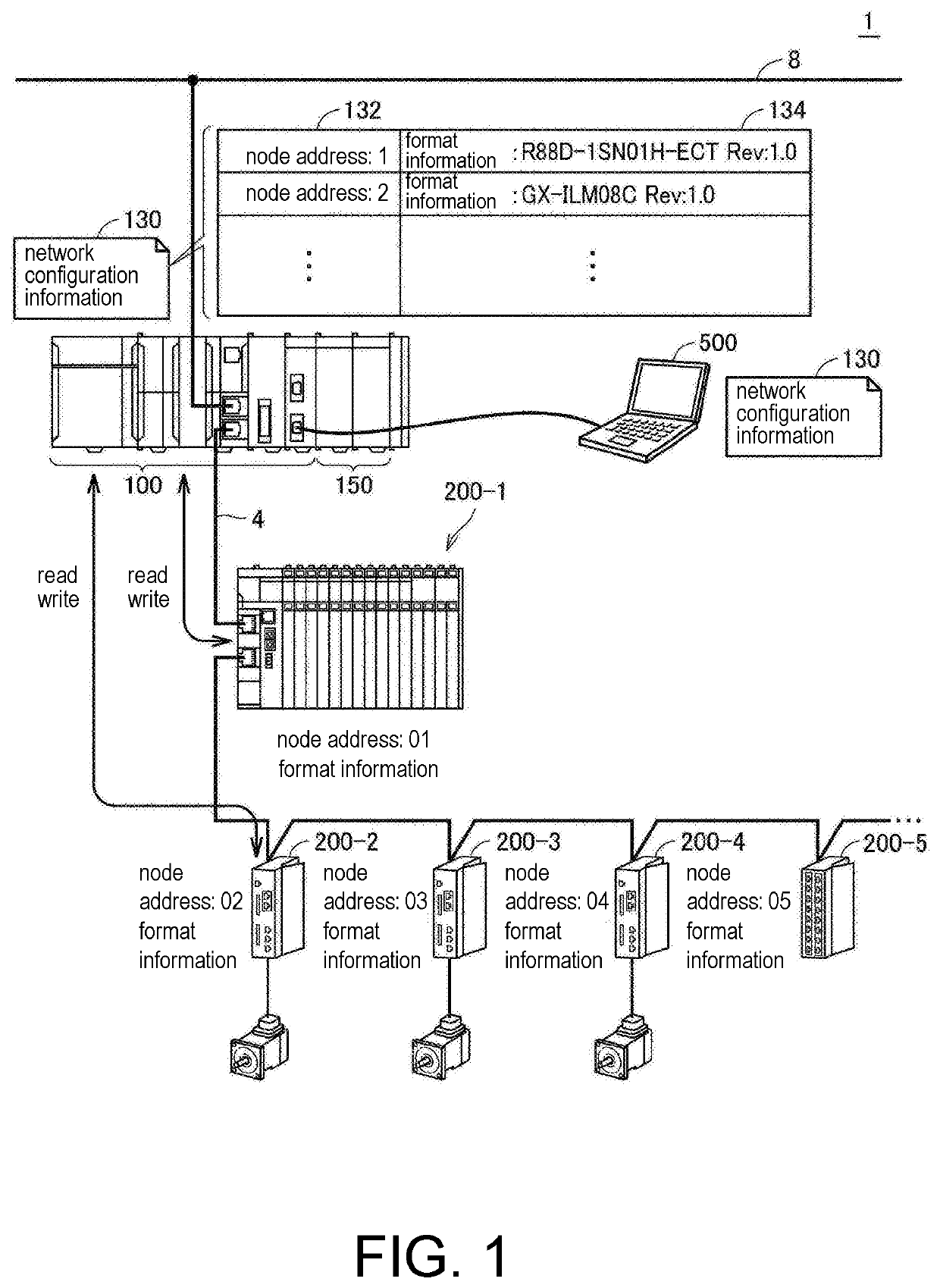
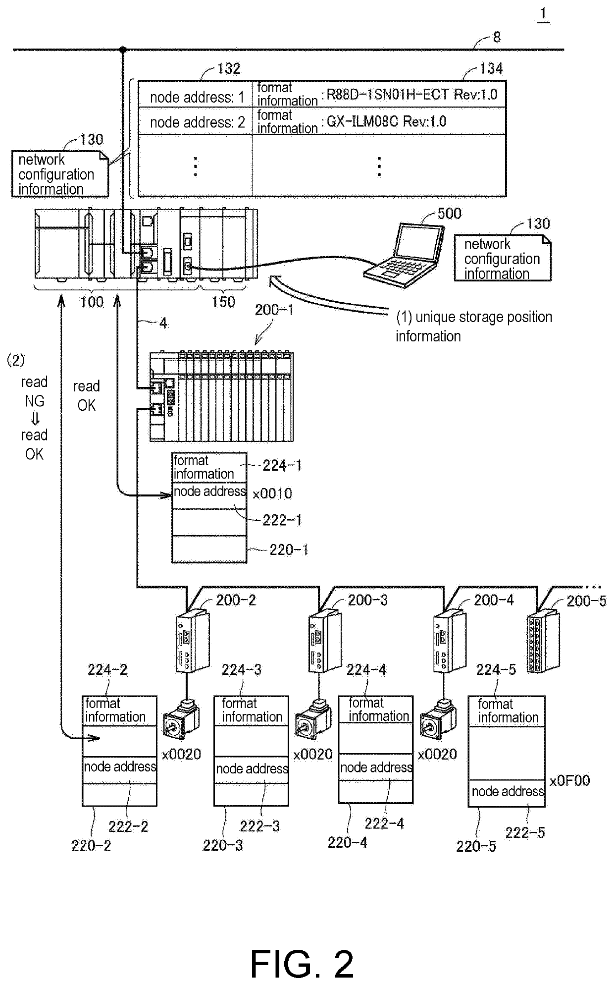
[0121]FIG. 8 is a diagram for illustrating a processing procedure of acquiring the node address in the control system 1 according to With reference to FIG. 8, the support apparatus 500 is connected to the control apparatus 100, and the support apparatus 500 stores one or a plurality of slave information files 600 in advance.
[0122]First, the support apparatus 500 requires the control apparatus 100 to acquire the actual network configuration ((1) actual configuration acquisition request). In response to the actual configuration acquisition request from the support apparatus 500, the control apparatus 100 accesses the target slave device 200 to acquire the format information 224 ((2) format information). The control apparatus 100 may acquire the StationAlias 228 in addition to the format information 224. Then, the control apparatus 100 sends the format information 224 acquired from the target slave device 200 to the support apparatus 500 ((3) format information).
[0123]The support appa...
embodiment 2
[0139]Therefore, in Embodiment 2, an example is described in which a slave information file server that manages the slave information file 600 is prepared and the unique storage position information is acquired while the slave information file server is also used.
[0140]That is, when the slave information file 600 held by the support apparatus 500 is older than the slave device 200 actually connected, the control apparatus 100 may access an external server to acquire a latest slave information file 600. By employing this example, the unique storage position information suitable for the actually connected slave device 200 can be reliably acquired.
[0141]FIG. 10 is a diagram for illustrating a processing procedure of acquiring a node address in the control system 1 according to Embodiment 2. In FIG. 10, description of the same processing as that shown in FIG. 8 is omitted.
[0142]With reference to FIG. 10, the support apparatus 500 is connected to the control apparatus 100, and the suppor...
embodiment 3
[0167]In Embodiment 3, a configuration is employed in which a plurality of slave information files 600 are held and a machine management server 800 is arranged which searches the target slave information file 600 according to the request from the control apparatus 100 or the like and responds to the unique storage position information from the description of the searched slave information file 600.
[0168]FIG. 12 is a diagram for illustrating a processing procedure of acquiring a node address in the control system 1 according to Embodiment 3. In FIG. 12, description of the same processing as the processing shown in FIG. 8 is omitted.
[0169]With reference to FIG. 12, the machine management server 800 that manages the slave information file 600 is connected to the information system network 8. The machine management server 800 appropriately collects and stores the slave information file 600 provided by a vendor (manufacturer or seller) of the slave device 200.
[0170]First, the control app...
PUM
 Abstract
Description
Claims
Application Information
 - R&D
- Intellectual Property
- Life Sciences
- Materials
- Tech Scout
- Unparalleled Data Quality
- Higher Quality Content
- 60% Fewer Hallucinations
Browse by: Latest US Patents, China's latest patents, Technical Efficacy Thesaurus, Application Domain, Technology Topic, Popular Technical Reports.
© 2025 PatSnap. All rights reserved.Legal|Privacy policy|Modern Slavery Act Transparency Statement|Sitemap|About US| Contact US: help@patsnap.com


