Pool drain suction outlet fitting

a technology for outlet fittings and pools, which is applied in the direction of gymnasiums, constructions, buildings, etc., can solve the problems of unsightly rectangular channels or high surface area grate drains configured as pool drains, and can be noticeable misalignment, so as to reduce turbulence

Active Publication Date: 2022-05-17
CUSTOM MOLDED PROD
View PDF5 Cites 0 Cited by
  • Summary
  • Abstract
  • Description
  • Claims
  • Application Information

AI Technical Summary

Benefits of technology

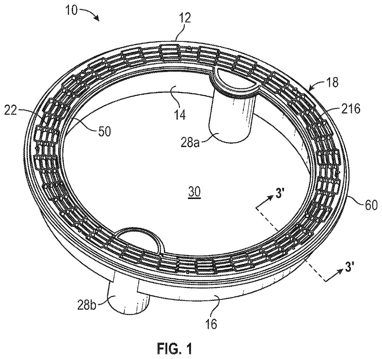
[0012]In another exemplary embodiment, at least one bridging element is included to provide additional support for a grate cover for covering the drainage channel and provide support to the inner and outer sidewalls preventing the walls from deformation due to stresses incurred as the surrounding surface material (gunite, cement, concrete, shotcrete, plaster, Pebble Tech®, etc.) cures. The surface material will exert force on the walls of the drain as the material cures whereby the inner and outer sidewalls would be pushed toward each other making the top opening narrower. This condition can prevent any optional drain cover from being installed into the opening. The bridging element also interrupts or substantially interrupts, depending on the size and structure of the bridging element, the top opening of the drainage channel to as to affect the flow of water into the drainage channel.
[0013]In another exemplary embodiment, the bridging element has a flow regulating feature depending downward into the drainage channel. The flow regulating feature interrupts or substantially interrupts, depending on the design of the flow regulating feature, the flow of water within the drainage channel. The flow interruption can reduce turbulence in the flow of water within the drainage channel, which can help prevent hair entrapment, and also can trap debris that enters the drainage channel through the grate cover thus preventing such debris from traveling into the water pumping system.

Problems solved by technology

For example, the common regulatory requirements for two pool drains structured so that a user likely would not become caught and stuck in the pool drain usually results in pool drains being configured as unsightly rectangular channels or high surface area grate drains.
If even slightly misaligned, the misalignment can be noticeable.

Method used


Image

  • Pool drain suction outlet fitting
  • Pool drain suction outlet fitting
  • Pool drain suction outlet fitting

Examples


Embodiment Construction

[0033]For a further understanding of the nature, function, and objects of the present invention, reference should now be made to the following detailed description. While detailed descriptions of the preferred embodiments are provided herein, as well as the best mode of carrying out and employing the present invention, it is to be understood that the present invention may be embodied in various forms. Therefore, specific details disclosed herein are not to be interpreted as limiting, but rather as a basis for the claims and as a representative basis for teaching one skilled in the art to employ the present invention in virtually any appropriately detailed system, structure, or manner.

[0034]Embodiments and aspects of the present invention provide a device and a system for draining an artificial body of water or pool that is not susceptible to the limitations and deficiencies of the prior art. The inventive concepts described herein, in certain non-limiting embodiments, allow for the ...


PUM


Abstract

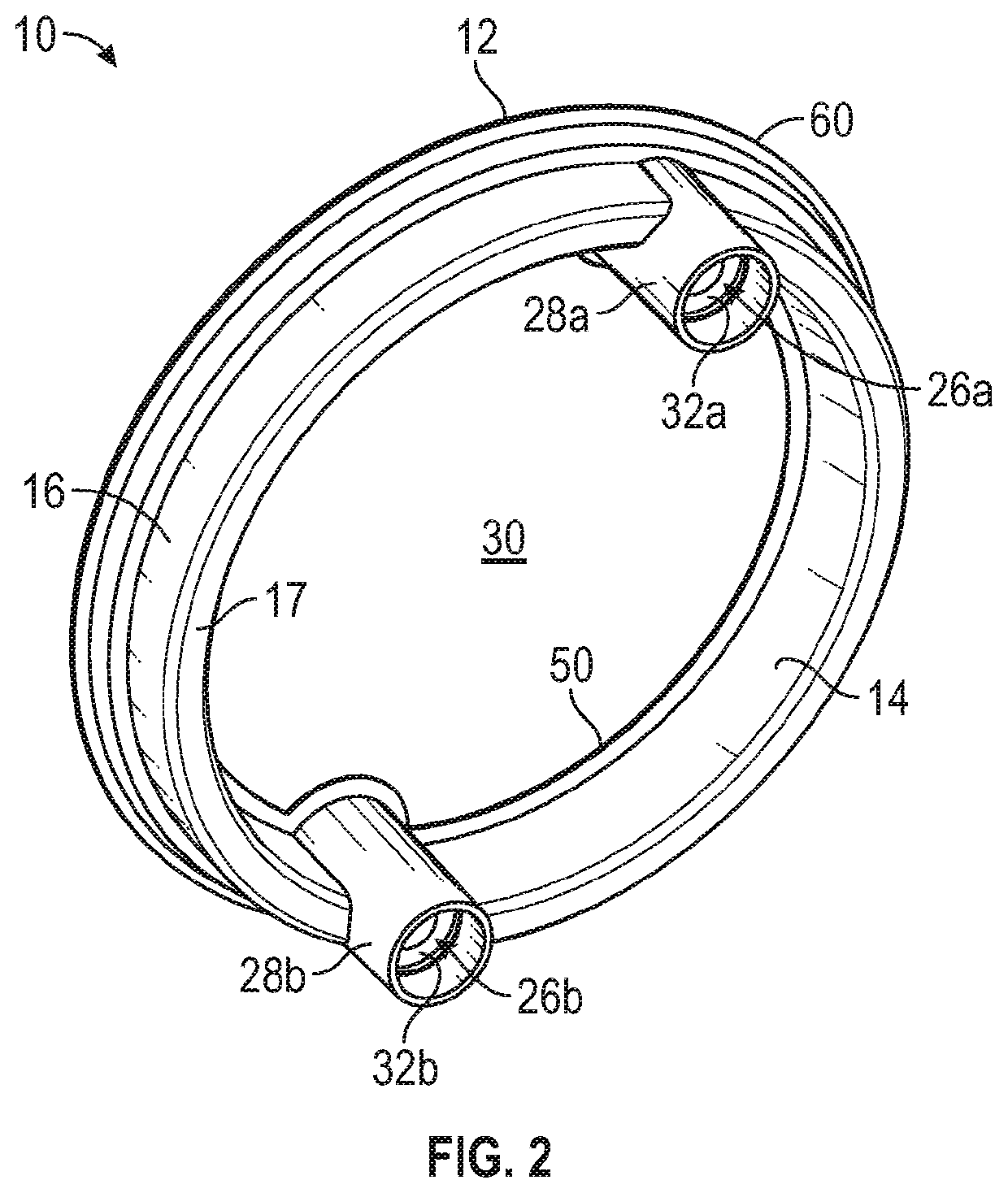
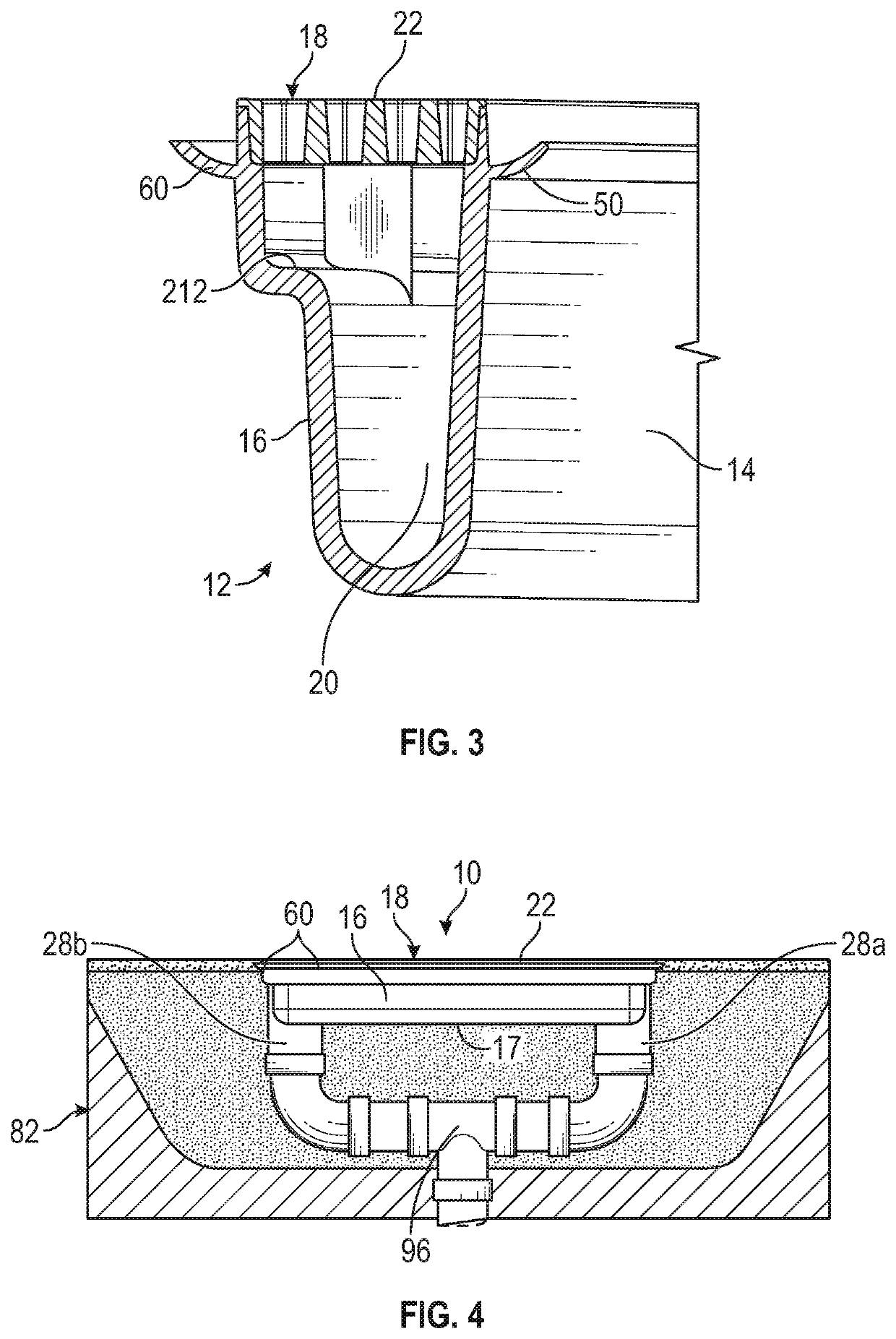
A pool drain or sump basin having elongated ring-shaped body, at least one and preferably a plurality of outlet ports about the ring-shaped body for allowing water to exit the drain, external peripheral flanges for mounting the drain, and an opening for allowing water to enter the drain, the ring-shaped body having an inner sidewall and outer sidewall, and open topside, and a closed bottom or floor closing off the bottom side of the body, bridging the gap between the inner sidewall and the outer sidewall, and creating a drainage channel. The body may have an optional cover configured as a removable or replacement cover with openings. The pool drain may have optional bridging elements and flow regulating elements for greater structural support and water flow regulation through the pool drain.

Description

CROSS REFERENCE TO RELATED APPLICATIONS[0001]This patent application claims priority on and the benefit of U.S. Provisional Patent Application No. 62 / 868,142 having a filing date of 28 Jun. 2019.BACKGROUND OF THE INVENTIONTechnical Field[0002]The present disclosure generally relates to pool suction outlet fittings, which also are commonly known in the art as pool drains or sumps, including sump basin fittings capable of allowing water to flow from the basin to a pump and filter for recirculation. More specifically, the present disclosure is directed to a recessed or inset system for draining or recirculating water in a water vessel or basin such as a spa, swimming pool, hot tub, garden bath, and the like. The present invention also is directed to the formation or insertion of a drainage / recirculation device into, or through, the side wall(s) or floor defining the water-containing portion of a spa, swimming pool, hot tub, garden bath, or the like.Prior Art[0003]Artificial bodies of w...

Claims


Application Information

Patent Timeline
Patent Type & Authority Patents(United States)
IPC IPC(8): E04H4/12
CPCE04H4/1236
Inventor SIMPSON, RICHARDPUGLIESE, ANGELO V.VOGTNER, ZACHARY T.
Owner CUSTOM MOLDED PROD
Why Eureka
Try Eureka