
Method for determining the position of the eye rotation center of the eye of a subject, and associated device

a technology of eye rotation center and eye rotation, applied in the field of optometry and optical metrology, can solve the problems of difficult to elaborate the complete geometric model of the eye, complicated physiological structure of the human eye,

Active Publication Date: 2022-05-17
ESSILOR INT CIE GEN DOPTIQUE
View PDF40 Cites 0 Cited by
  • Summary
  • Abstract
  • Description
  • Claims
  • Application Information

AI Technical Summary

Benefits of technology

[0016]Therefore one object of the invention is to provide an easy-to-implement method to determine quickly an approximate value of the position of the ERC of a subject, in particular without the need of using a reference accessory.
[0030]With this apparatus, one gets easily the 3D profile of the cornea and one can then find the ellipsoid which models the cornea in the best way.

Problems solved by technology

As the physiological structure of a human eye is very complicated, a complete geometric model of an eye is very hard to elaborate, taking into account all the optical surfaces and physical media involved in the optical path of the light through the eye.

Method used


Image

  • Method for determining the position of the eye rotation center of the eye of a subject, and associated device
  • Method for determining the position of the eye rotation center of the eye of a subject, and associated device

Examples


Embodiment Construction

[0066]The following description, enriched with joint drawings that should be taken as non limitative examples, will help understand the invention and figure out how it can be realized.

[0067]On joint drawings:

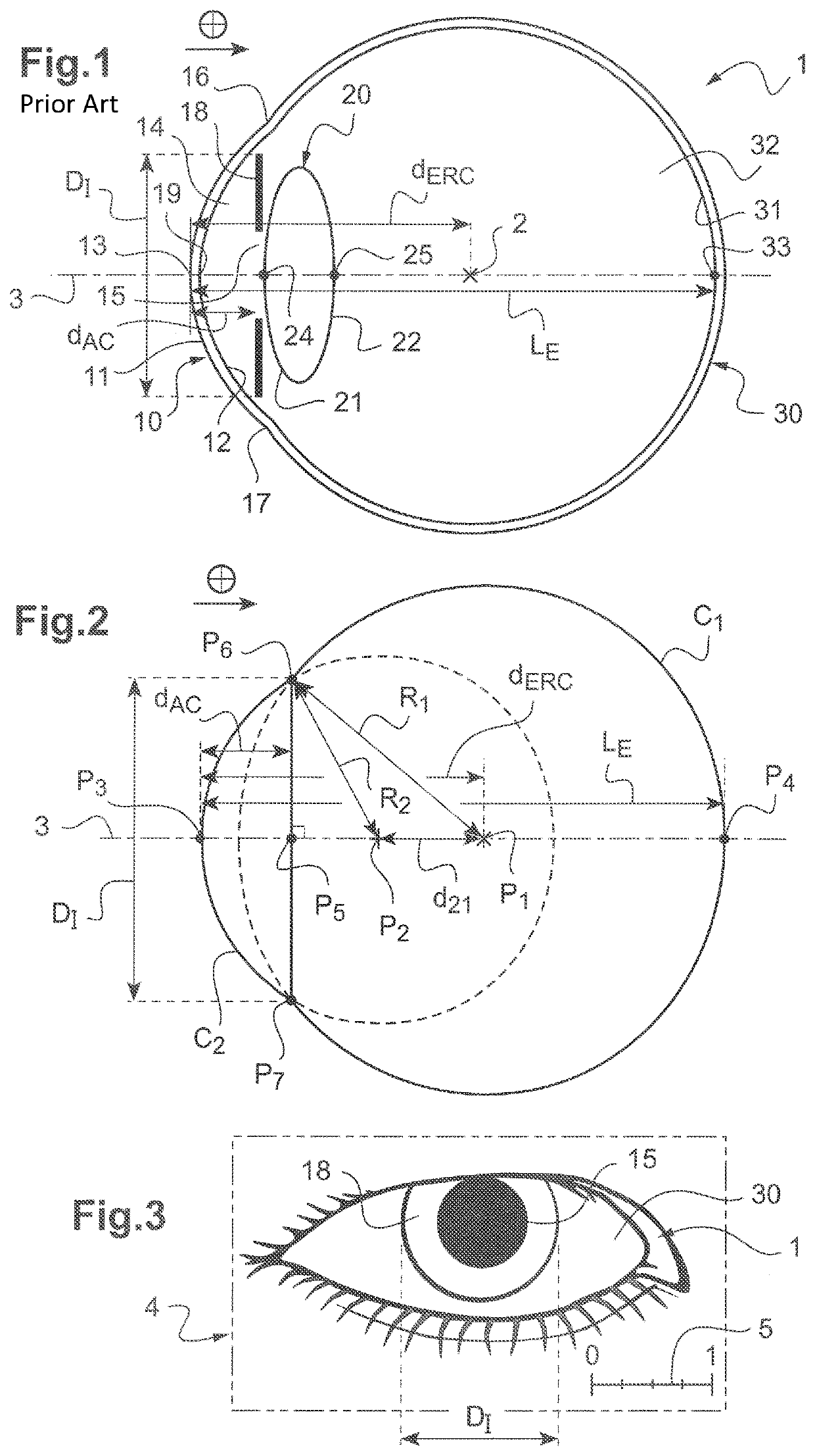
[0068]FIG. 1 is a section view of the structure of the eye of a subject;

[0069]FIG. 2 is a schematic view of one geometric model used for the invention;

[0070]FIG. 3 is a facial image of the eye of a subject acquired by a device according to the invention;

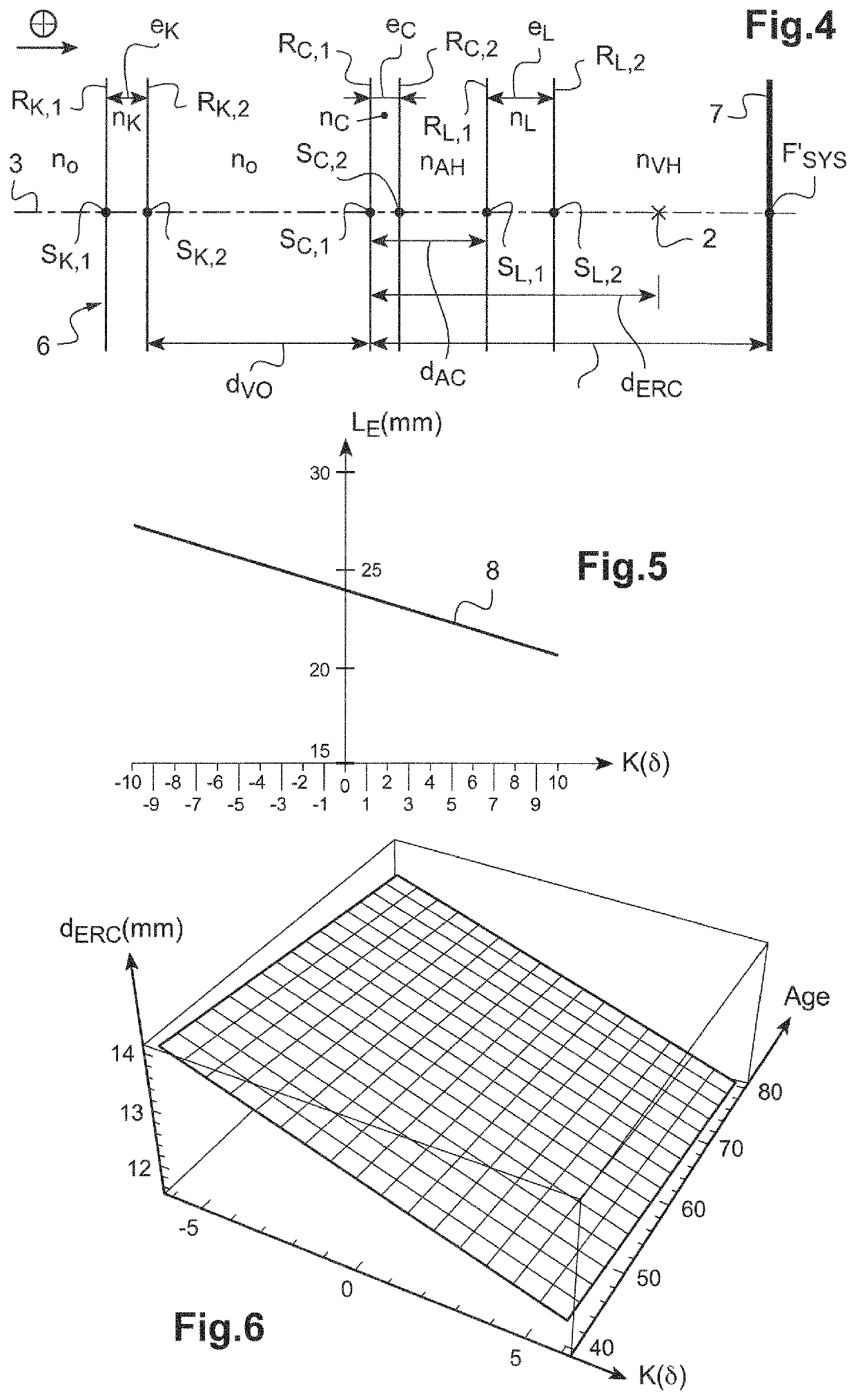
[0071]FIG. 4 is a paraxial representation of the optical model used for the eye of the subject;

[0072]FIG. 5 is a curve showing the variation of the length of the eye as a function of the outer diameter of the iris of the subject aged 60;

[0073]FIG. 6 is a 3D plot showing the variation of the position of the eye rotation center as a function of age of the subject and need of visual correction for the subject.

[0074]We represent on FIG. 1 a section view of a simplified physiological structure of a human eye 1 (one the two eyes of a s...


PUM


Abstract

Disclosed is a method for determining the position of the eye rotation center of a subject's eye including: providing a geometric model of an eye, the eye being modeled with one sphere for the sclera and one ellipsoid for the cornea of the eye, the position of the eye rotation center being the distance between a center of the sclera and an apex of the cornea and being determined based on a set of personal parameters including a first geometric dimension of the eye, each personal parameter distinct from the position of the eye rotation center; determining a value of each personal parameter; and determining a first approximate value of eye position rotation center based on the geometric model using the personal parameters. Also disclosed is a method for calculating a personalized ophthalmic lens for the eye using such center, as well as a device implementing this method.

Description

TECHNICAL FIELD OF THE INVENTION[0001]The invention relates to the fields of optometry and optical metrology.[0002]More precisely, the invention relates to a device and a method for determining the position of the eye rotation center of the eye of a subject.[0003]The invention relates also to a method for calculating an ophthalmic lens using this method.BACKGROUND INFORMATION AND PRIOR ART[0004]In order to customize the ophthalmic lens for a specific subject, geometrical, postural and behavioral parameters of the subject and / or of the subject with his / her eyeglasses need to be determined.[0005]Among these parameters, the position of a center of rotation of at least one of the eyes is determined.[0006]Movements of each eye of a subject can generally be considered as being a combination of rotations about a particular point that is referred to as the center of rotation of the eye or “eye rotation center”, hereinafter also referred to as ERC.[0007]It is desirable to determine the posit...

Claims


Application Information

Patent Timeline
Patent Type & Authority Patents(United States)
IPC IPC(8): G02C7/02G02C13/00A61B3/00
CPCG02C7/027A61B3/0025G02C7/028G02C13/005
Inventor GRAND-CLEMENT, DIDIER
Owner ESSILOR INT CIE GEN DOPTIQUE
Learn More