
Multi-wavelength light radiating apparatus

a light-radiating apparatus and multi-wavelength technology, applied in the direction of optical radiation measurement, instruments, spectrometry/spectrophotometry/monochromators, etc., can solve the problems of inability to say that it is necessarily a suitable apparatus for analyzing, cannot be easily introduced into laboratories from the standpoint, and can only be used in limited techniques, etc., to achieve low cost and low cost , the effect of small siz

Active Publication Date: 2022-06-28
TOYOHASHI UNIVERSITY OF TECHNOLOGY
View PDF13 Cites 0 Cited by
  • Summary
  • Abstract
  • Description
  • Claims
  • Application Information

AI Technical Summary

Benefits of technology

The present invention proposes a multiwavelength-light-radiating apparatus that is low-cost and small-sized. This apparatus uses optical waveguides to guide monochromatic lights to individual samples, resulting in simultaneous irradiation of multiple samples with each sample receiving one monochromatic light. This approach eliminates the need for large equipment and increases the wavelength resolving power of the monochromatic light while maintaining light intensity. The use of a continuous light source and diffracting part further facilitates this goal.

Problems solved by technology

Nevertheless, the above-mentioned large-size spectrograph is large equipment on the scale of approximately 10 m and therefore cannot easily be introduced into laboratories from the standpoints of size and cost.
In addition, it cannot be said that it is necessarily a suitable apparatus for analyzing, for example, extremely minute, small quantities of samples such as cells of organisms.
In addition, a technique is also conceivable in which numerous monochromatic lights are respectively radiated onto samples using LEDs (light-emitting diodes); however, there is a limit to this technique from the viewpoint of wavelength resolving power, and it is problematic to sufficiently conduct detailed research into the action spectrum analysis described above.

Method used


Image

  • Multi-wavelength light radiating apparatus
  • Multi-wavelength light radiating apparatus
  • Multi-wavelength light radiating apparatus

Examples


first embodiment

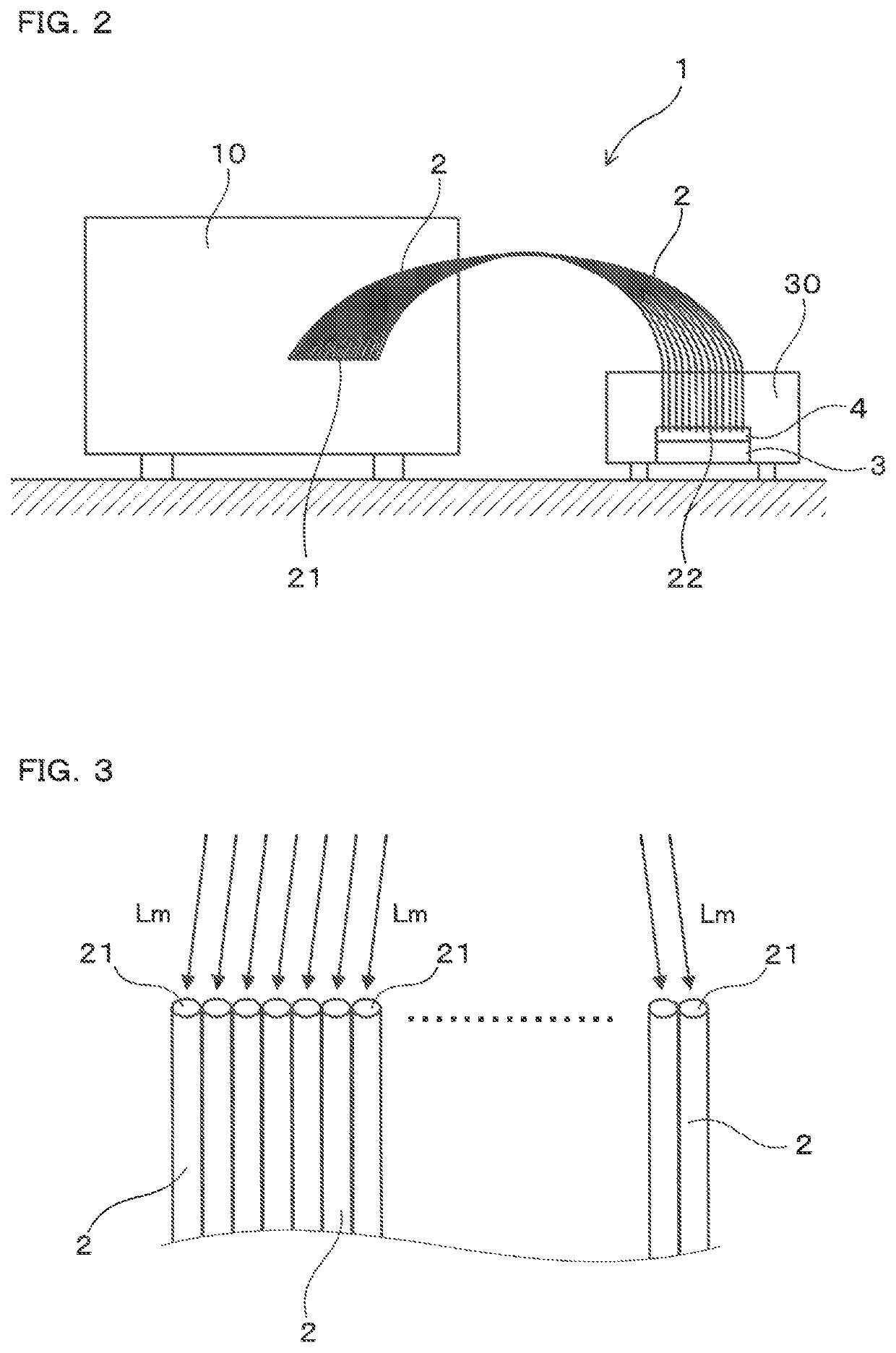
[0052]An embodiment of the multiwavelength-light-radiating apparatus will be explained, with reference to FIG. 1 to FIG. 8.

[0053]A multiwavelength-light-radiating apparatus 1 of the present embodiment comprises a light source 11, a diffracting part 12, numerous optical fibers 2, and a sample-placement part 3, as shown in FIG. 1 and FIG. 2.

[0054]The light source 11 radiates continuous light Lc. The diffracting part 12 diffracts the continuous light Lc into numerous monochromatic lights Lm, whose wavelengths differ from one another, and emits such. With regard to the optical fibers 2, the monochromatic lights Lm emitted from the diffracting part 12 are individually introduced from incident ends 21 and emitted as monochromatic irradiation lights Li from output ends 22.

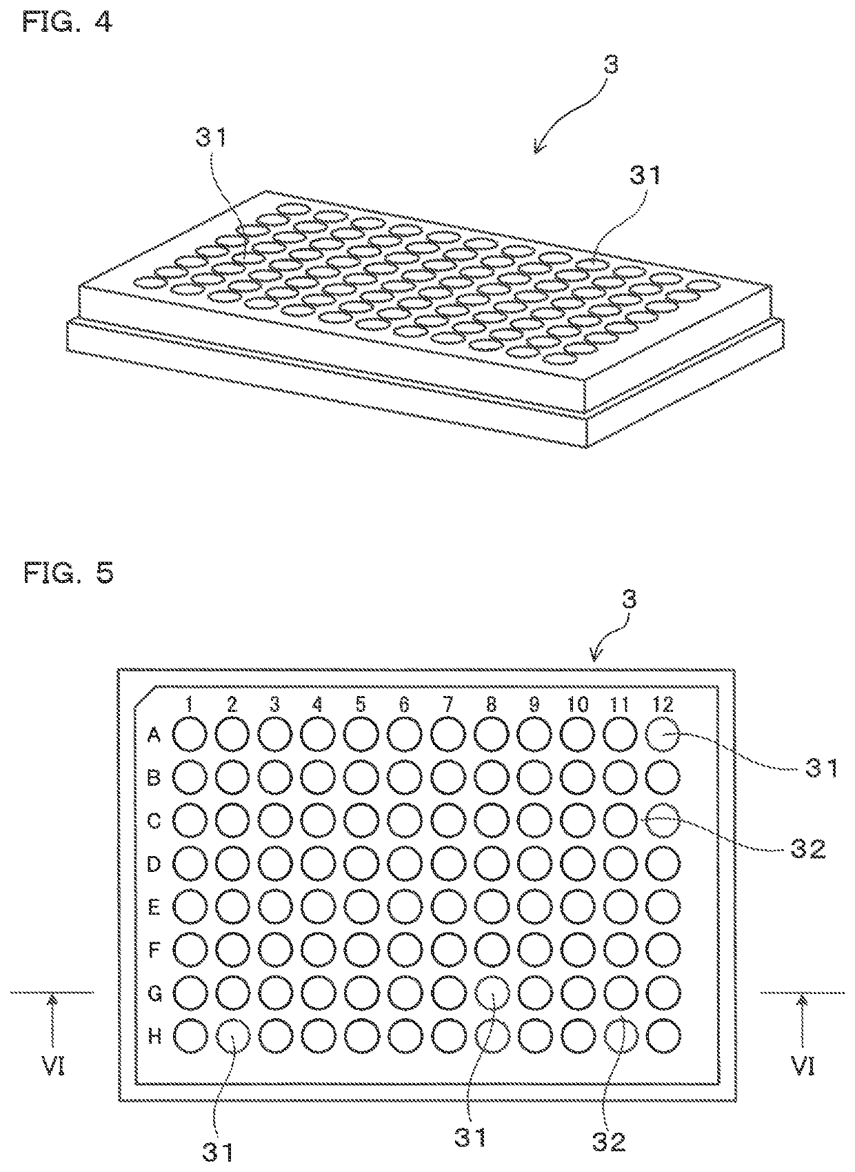
[0055]As shown in FIG. 4 to FIG. 7, the sample-placement part 3 comprises numerous wells 31, which are disposed opposing the output ends 22 of the corresponding optical fibers 2, each well opposing its corresponding outpu...

second embodiment

[0096]As shown in FIG. 9, in the multiwavelength-light-radiating apparatus 1 of the present embodiment, the sample-placement part 3 comprises a temperature-adjusting part 33 for adjusting the temperature of the samples s inside the wells 31.

[0097]The temperature-adjusting part 33 is disposed on a lower side of the sample-placement part 3. Furthermore, it is configured so that the temperature of the samples s inside the numerous wells 31 can be equalized. The temperature-adjusting part 33 can be configured as one that comprises, for example, a thermoelectric heater, a Peltier device, or the like.

[0098]Other structural elements are the same as in the first embodiment. It is noted that those symbols used in the second embodiment and onward that are identical to the symbols used in the previously recited embodiment indicate, unless otherwise specified, structural elements that are the same as those in the previously recited embodiment.

[0099]In the present embodiment, the monochromatic i...

third embodiment

[0101]The present embodiment is an embodiment in which temperature adjustment of the samples placed on the sample-placement part 3 is performed using, as the temperature-adjusting part, one that has a housing space that can be maintained at a prescribed temperature.

[0102]That is, the sample-placement part 3 on which the numerous samples are placed is housed inside the housing space. The interior of the housing space is a heat-insulating structure that is isolated from external air and that can inhibit the effect of the external-air temperature. Furthermore, the interior of the housing space is adjusted to a prescribed temperature using a temperature-adjusting means such as a Peltier device.

[0103]The light source 11, the diffracting part 12, and the like are disposed outside of the housing space, and the samples are disposed inside the housing space. Consequently, the optical fibers 2 are disposed such that they are inserted through the interior and the exterior of the housing space....


PUM

PropertyMeasurementUnit
full width at half maximumaaaaaaaaaa
peak wavelengthsaaaaaaaaaa
wavelength rangesaaaaaaaaaa

Abstract

A multiwavelength-light-radiating apparatus (1) includes: a light source (11) that radiates continuous light (Lc); a diffracting part (12) that diffracts the continuous light (Lc) into numerous monochromatic lights (Lm), whose wavelengths differ from one another, and emits the numerous monochromatic lights (Lm); numerous optical waveguides (2) that respectively transmit the numerous monochromatic lights (Lm) emitted from the diffracting part (12) from incident ends (21) to output ends (22) where the numerous monochromatic lights (Lm) are respectively emitted; and a sample-placement part (3) that holds numerous samples such that the output ends (22) of the numerous optical waveguides (2) respectively oppose the samples. The numerous monochromatic irradiation lights, whose wavelengths differ from one another, are arranged to be radiated simultaneously onto the numerous samples, one light per sample.

Description

CROSS-REFERENCE[0001]This application is the US national stage of International Patent Application No. PCT / JP2018 / 014454 filed on Apr. 4, 2018, which claims priority to Japanese Patent Application No. 2017-074637 filed on Apr. 4, 2017.TECHNICAL FIELD[0002]The present invention relates to a multiwavelength-light-radiating apparatus configured such that numerous monochromatic irradiation lights can be radiated simultaneously onto numerous samples, each light onto its corresponding sample.BACKGROUND ART[0003]Research called optogenetics (optogenetics), which controls physiological phenomena of organisms using light irradiation, has been conducted in recent years. Within that research, there is research being conducted to investigate the wavelength dependency of physiological responses of organisms to light. That is, there is an analysis technique (action spectrum analysis) that irradiates an organism with lights of various wavelengths and quantifies the physiological responses thereto....

Claims


Application Information

Patent Timeline
Patent Type & Authority Patents(United States)
IPC IPC(8): G01N21/63G01N21/03G02B6/42
CPCG01N21/63G01N21/03G02B6/4215G01N2201/0453G01N2201/0635G01J3/10G01N21/253G01N2201/0826G01N21/0332G02B6/4249G02B6/4292
Inventor HIROSE, YUU
Owner TOYOHASHI UNIVERSITY OF TECHNOLOGY
Learn More