
Pixel array substrate with narrow peripheral area and narrow bezel design of display panel

a technology of pixel array substrate and display panel, which is applied in the direction of instruments, semiconductor devices, electrical apparatus, etc., can solve the problems of inability to achieve the narrow bezel design of the display panel, and the significant reduction of the layout space of the circuit in the peripheral area

Active Publication Date: 2022-07-05
AU OPTRONICS CORP
View PDF5 Cites 1 Cited by
  • Summary
  • Abstract
  • Description
  • Claims
  • Application Information

AI Technical Summary

Benefits of technology

The present patent application provides a pixel array substrate with a narrower peripheral area and better design margin for bonding pads and connecting lines. This helps to achieve a narrower bezel design of the display panel and increases the design margin for circuits. The electrical resistivity of the connecting lines is greater than the electrical resistivity of the signal lines, which can improve the operating electricity of the pixel array substrate. Disposing two demultiplexers in different regions of the pixel array substrate can increase the design margin for the demultiplexers and improve the operating electricity of the pixel array substrate.

Problems solved by technology

However, as the resolution of the display panel continues to increase, the number of driving signal lines also increases, and the number of peripheral traces connected to the driving signal lines results in a significant reduction in the layout space of the circuit in the peripheral area.
Even though the use of demultiplexers reduces the number of peripheral traces, it still takes up part of the peripheral area, making the narrow bezel design of the display panel impossible to achieve.

Method used


Image

  • Pixel array substrate with narrow peripheral area and narrow bezel design of display panel
  • Pixel array substrate with narrow peripheral area and narrow bezel design of display panel
  • Pixel array substrate with narrow peripheral area and narrow bezel design of display panel

Examples


first embodiment

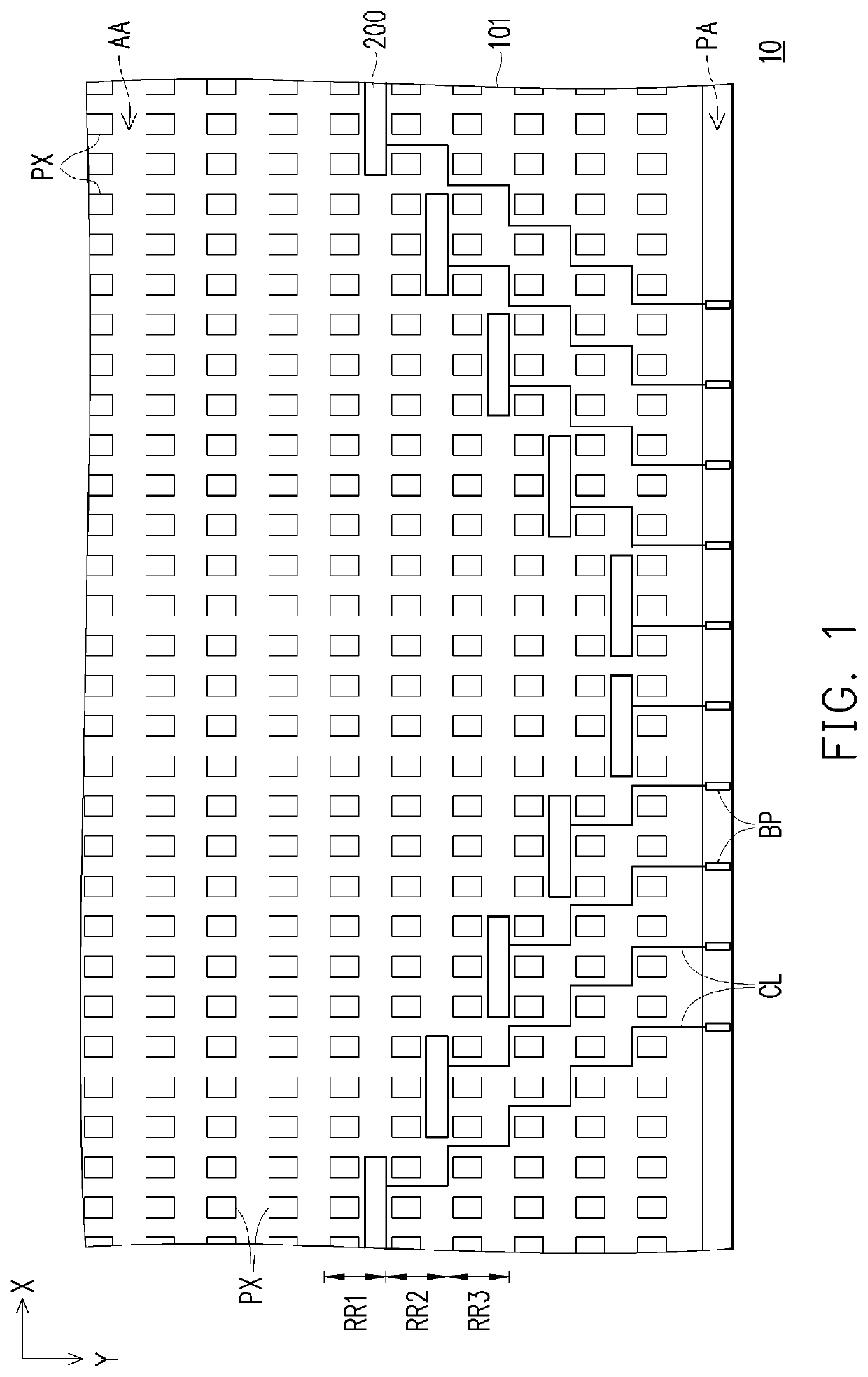
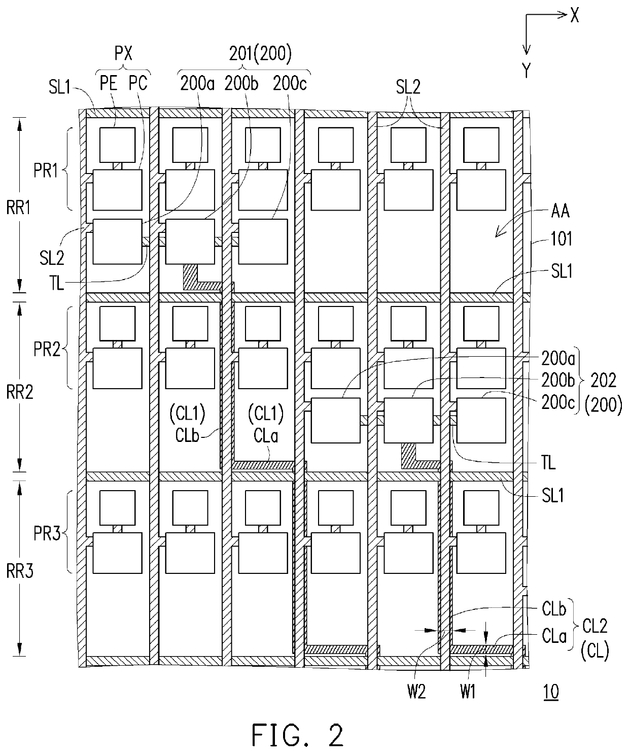
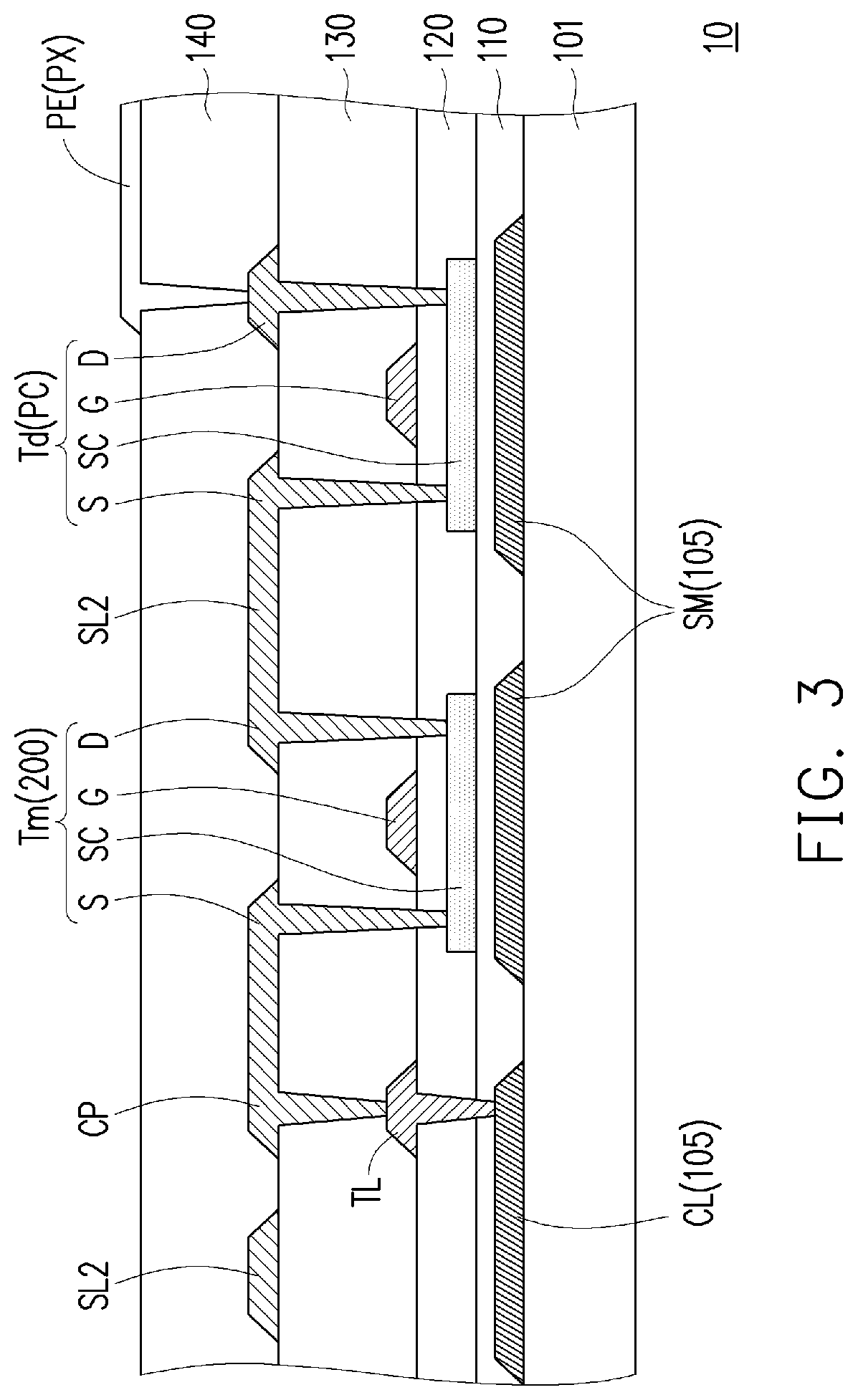
[0022]FIG. 1 is a schematic top view of a pixel array substrate according to the present application. FIG. 2 is an enlarged schematic view of a partial area of the pixel array substrate of FIG. 1. FIG. 3 is a partial cross-sectional view of the pixel array substrate of FIG. 2. In particular, for the sake of clarity, FIG. 1 omits the first signal line SL1 and the second signal line SL2 of FIG. 2, and FIG. 2 omits the buffer layer 110, the gate insulating layer 120, the interlayer insulating layer 130 and the planarization layer 140 of FIG. 3.

[0023]Referring to FIG. 1 and FIG. 2, the pixel array substrate 10 includes a substrate 101, a plurality of first signal lines SL1, a plurality of second signal lines SL2 and a plurality of pixels PX. The substrate 101 has a display area AA and a peripheral area PA disposed on one side of the display area AA. The first signal lines SL1 are arranged on the substrate 101, and define a plurality of row regions of the display area AA, such as the row...

second embodiment

[0039]FIG. 4 is a cross-sectional view of a pixel array substrate of the present application. Referring to FIG. 4, the main difference between the pixel array substrate 11 of the present embodiment and the pixel array substrate 10 of FIG. 3 lies in the arrangement of the connecting lines. In the present embodiment, the connection line CL1 and the connection line CL2A are belong to different film layers; for example, the connection line CL1 is formed in the first conductive layer 105, and the connection line CL2A is formed in the second conductive layer 155, and the first conductive layer 105 is located between the second conductive layer 155 and the substrate 101.

[0040]In detail, the planarization layer 140A of the present embodiment may be a stacked structure of the first planarization sublayer 141 and the second planarization sublayer 142, and the second conductive layer 155 is located between the first planarization sublayer 141 and the second planarization sublayer 142. The con...

third embodiment

[0041]FIG. 5 is a schematic top view of a pixel array substrate according to the present application. FIG. 6 is an enlarged schematic view of a partial area of the pixel array substrate of FIG. 5. For the sake of clarity, FIG. 5 does not show the first signal line SL1 and second signal line SL2 of FIG. 6. Referring to FIG. 5 and FIG. 6, the main difference between the pixel array substrate 12 of the present embodiment and the pixel array substrate 10 of FIG. 1 lies in the arrangement of the demultiplexers and the connection lines in the display area AA. In the present embodiment, multiple demultiplexers 200 are respectively disposed in the row region RR4, the row region RR5 and the row region RR6 adjacent to the peripheral area PA, and any two adjacent demultiplexers 200 are shifted from each other in the direction X. It is noted that by distributing these demultiplexers 200 in different row regions, the design margin of demultiplexer circuit (such as the number of control lines cor...


PUM


Abstract

A pixel array substrate including a substrate, a plurality of first signal lines, a plurality of second signal lines, a plurality of pixels, a first demultiplexer, a second demultiplexer, a first connecting line and a second connecting line is provided. The substrate has a display area. The first signal lines are arranged on the substrate and define a first row region and a second row region of the display area. The pixels are arranged into a first pixel row and a second pixel row which are respectively disposed in the first row region and the second row region. The first demultiplexer is disposed in the first row region and electrically connected to a part of the second signal lines. The second demultiplexer is disposed in the second row region and electrically connected to another part of the second signal lines. The first connecting line is electrically connected to the first demultiplexer. The second connecting line is electrically connected to the second demultiplexer. The electrical resistivity of the first connecting line and the second connecting line is greater than the electrically resistivity of the first signal lines and the second signal lines.

Description

CROSS-REFERENCE TO RELATED APPLICATION[0001]This application claims the priority benefit of Taiwan application serial no. 108135746, filed on Oct. 2, 2019. The entirety of the above-mentioned patent application is hereby incorporated by reference herein and made a part of this specification.BACKGROUNDTechnical Field[0002]The present application relates to a display technology, and particularly to a pixel array substrate.Description of Related Art[0003]Mobile devices such as smartphones and tablets equipped with retina displays have brought consumers an unprecedented visual experience, but have also led to the development of headset display technologies such as Virtual Reality (VR), Augmented Reality (AR) and Mixed Reality (MR). To make the display of these applications more realistic, an ultra-high resolution display panel is essential.[0004]However, as the resolution of the display panel continues to increase, the number of driving signal lines also increases, and the number of per...

Claims


Application Information

Patent Timeline
Patent Type & Authority Patents(United States)
IPC IPC(8): G09G3/20
CPCG09G3/20G09G2300/0439G09G2310/0297H01L27/1214H01L27/124H01L27/156G02F1/136286G02F1/13452H10K59/12G09G2300/0426G09G2300/0408G09G2310/0281G09G2320/0223
Inventor HUANG, SHU-HAOSU, SUNG-YU
Owner AU OPTRONICS CORP
Learn More