
Casella hydraulic variable compression ratio piston

a compression ratio and piston technology, applied in the direction of trunk pistons, machines/engines, plungers, etc., can solve the problems of slow compression rate, loss of oil by lifters, and contraction of lifters, so as to control the compression ratio, reduce combustion and engine load, and maintain the compression ratio

Active Publication Date: 2022-07-12
CASELLA PAULO E
View PDF1 Cites 0 Cited by
  • Summary
  • Abstract
  • Description
  • Claims
  • Application Information

AI Technical Summary

Benefits of technology

The invention changes compression by moving the piston part way relative to the connecting rod to prevent pre-detonation from high combustion pressure. This movement is made possible by rotating an eccentric piston pin. The position of the piston remains fixed at its current compression ratio, only changing when power levels and inertia change. This control is achieved with a combination of return springs and a lifter that controls the position of the eccentric. The lifter gradually wears down and expands at higher engine loads, only allowing the eccentric to move when there is an increase in combustion pressure. This invention allows for better control of compression ratio to improve engine performance.

Problems solved by technology

The lifter eventually loses oil and contracts, but very slowly at lower combustion and engine loads.

Method used


Image

  • Casella hydraulic variable compression ratio piston
  • Casella hydraulic variable compression ratio piston
  • Casella hydraulic variable compression ratio piston

Examples


Embodiment Construction

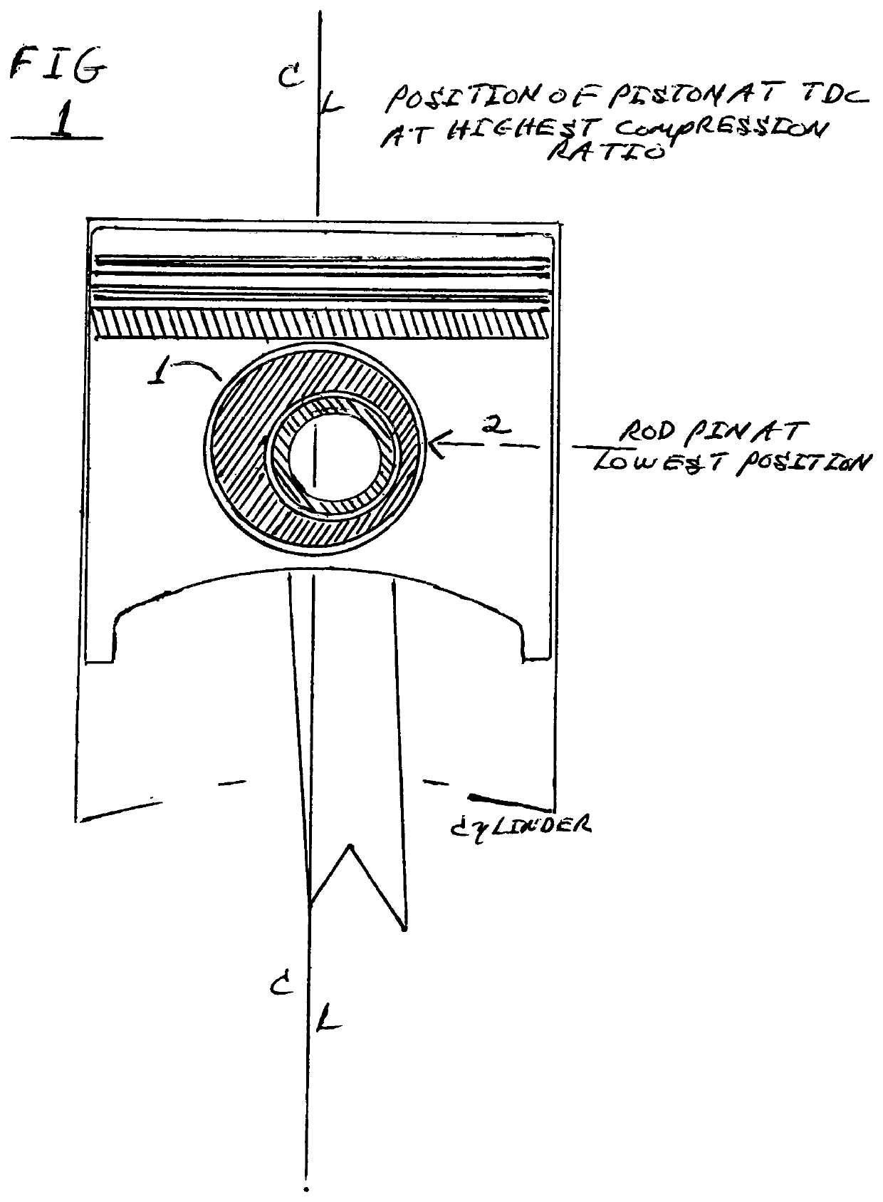
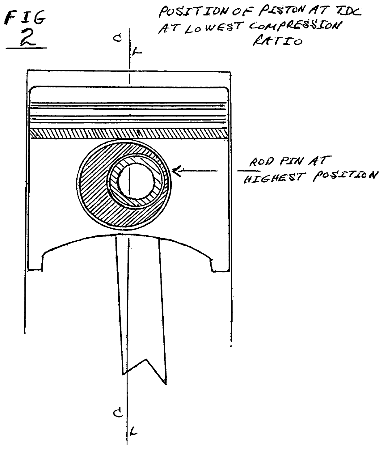
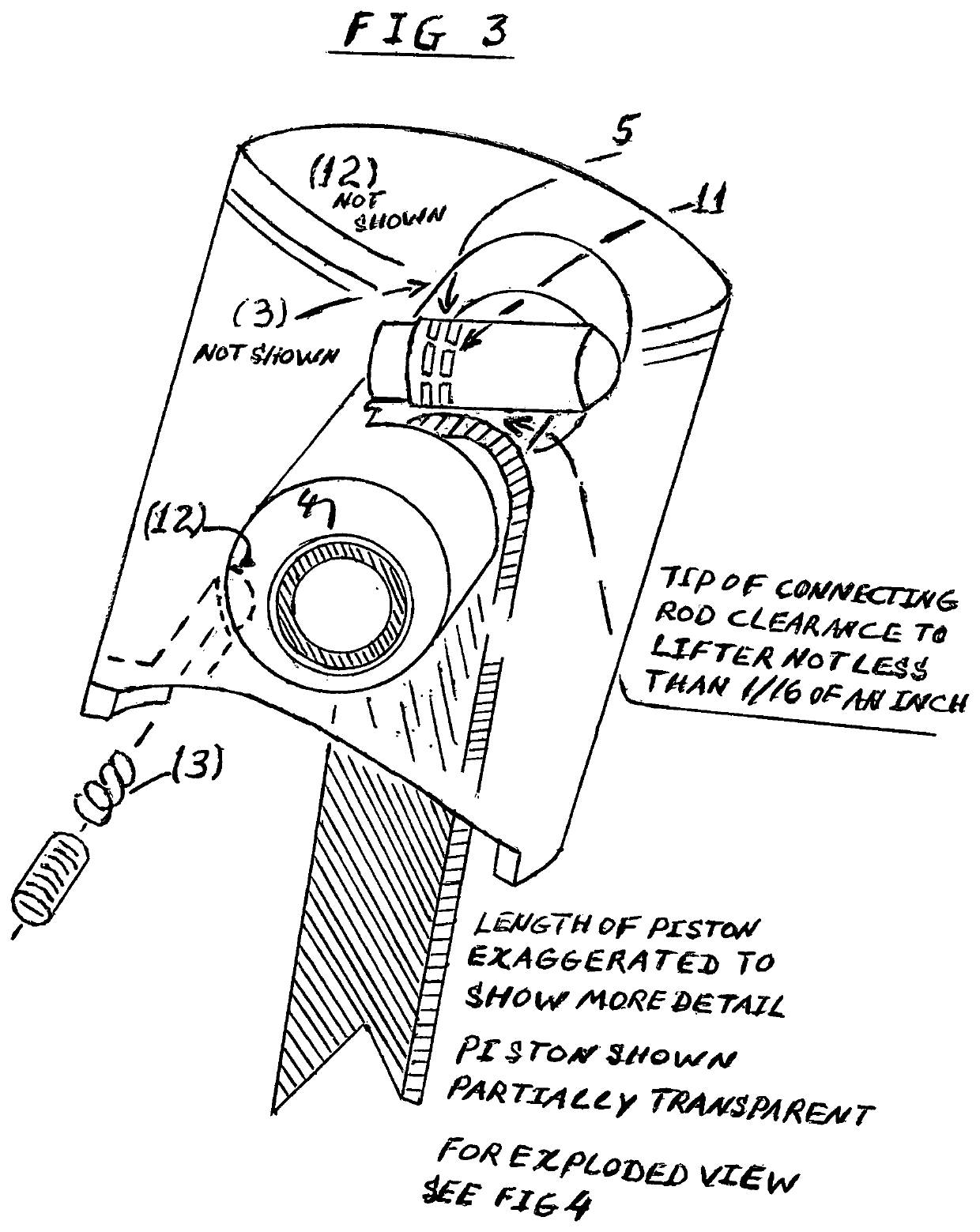
[0017]The piston achieves variable compression by changing its vertical position relative to the connecting rod. A free moving eccentric (1). FIG. 1, is fitted into the body of the piston. The connecting rod pin (2) FIG. 1, in turn fits into the eccentric. A middle clearance cut-out (13) FIG. 5, is cut into the eccentric for connecting rod clearance. Another smaller cut-out (6) FIG. 4 is cut into the eccentric middle clearance (13) FIG. 5 to accept the opposing lifter piston (10) FIG. 4. The default / initial compression ratio of the cylinder is at its highest, for example 12:1.

[0018]With increases in engine power, the combustion forces atop the piston can reach upwards to 300 lbs, for example, but inertial forces acting on the piston / connecting rod assembly at top dead center (TDC), and bottom dead center (BDC) are magnitudes higher, up to 3000 lbs at highest engine power and rpm. The variable compression ratio piston does not rely on the combustion forces. The piston, rather, relies...


PUM


Abstract

The invention in question relates, in particular, to a hydraulic variable compression ratio piston comprising a full floating eccentric mounted in the body of said piston, wherein the eccentric accepts a piston pin, with the pin in turn, accepting the small end of the connecting rod. The eccentric moves in a circular manner against the force of preloaded springs installed at the bottom of the piston, thereby allowing the piston to move up or down relative to the connecting rod. An adjustment mechanism within the piston comprising of a combination of said preloaded springs and a lifter acting against the movement of the eccentric, holds the piston's current position relative to the connecting rod until an increase or decrease in combustion forces act upon the piston and changes the compression ratio.

Description

BACKGROUND OF THE INVENTION(1) Field of the Invention[0001]The present invention relates to a variable compression ratio piston which changes height relative to a common connecting rod to modify the compression ratio in a typical internal combustion engine.(2) Description of the Related Art[0002]In modern internal combustion engines, a higher compression ratio yields more power and greater fuel efficiency. Compression ratio is thus defined as the largest cylindrical volume atop the piston, at bottom dead enter, divided by the smallest cylindrical volume atop the same piston at top dead center. By definition, a fixed compression ratio only allows combustion efficiency to occur at maximum engine torque and load with only partial combustion at lesser loads due to the partial filling of the cylinder. Partial filling occurs when only small injection of fuel and air are required for smaller engine loads or when the total mix of fuel and air does not completely fill the cylinder due to air...

Claims


Application Information

Patent Timeline
Patent Type & Authority Patents(United States)
IPC IPC(8): F02B75/04F16J1/08F16J1/18
CPCF02B75/044F16J1/08F16J1/18
Inventor CASELLA, PAULO E.
Owner CASELLA PAULO E
Learn More