Power conversion system and method

a power conversion and power technology, applied in the direction of electric variable regulation, process and machine control, instruments, etc., can solve the problem of saving a lot of cos

Active Publication Date: 2022-07-19
SIGNIFY HLDG BV
View PDF14 Cites 0 Cited by
  • Summary
  • Abstract
  • Description
  • Claims
  • Application Information

AI Technical Summary

Benefits of technology

[0010]It is a concept of the invention to simplify system upgrades for power conversion systems, for example when a power or energy requirement changes. A modular system using multiple conversion units may be used, wherein the multiple conversion units are connected in series and share the input voltage provided to the system, so that additional units may be added to respond to an increased input voltage. In a series connection, the new conversion unit is added at the converter site by a short wiring to the existing conversion units, and the existing long wiring between the solar cell site and the converter site does not need to be modified, which saves a lot of cost. The concept of the invention also proposes a solution to control the series connected conversion units to reach the maximum power point synchronously such that the series connected conversion units balance the output of an energy source, e.g. solar cell array.

Problems solved by technology

In a series connection, the new conversion unit is added at the converter site by a short wiring to the existing conversion units, and the existing long wiring between the solar cell site and the converter site does not need to be modified, which saves a lot of cost.

Method used


Image

  • Power conversion system and method
  • Power conversion system and method

Examples


Embodiment Construction

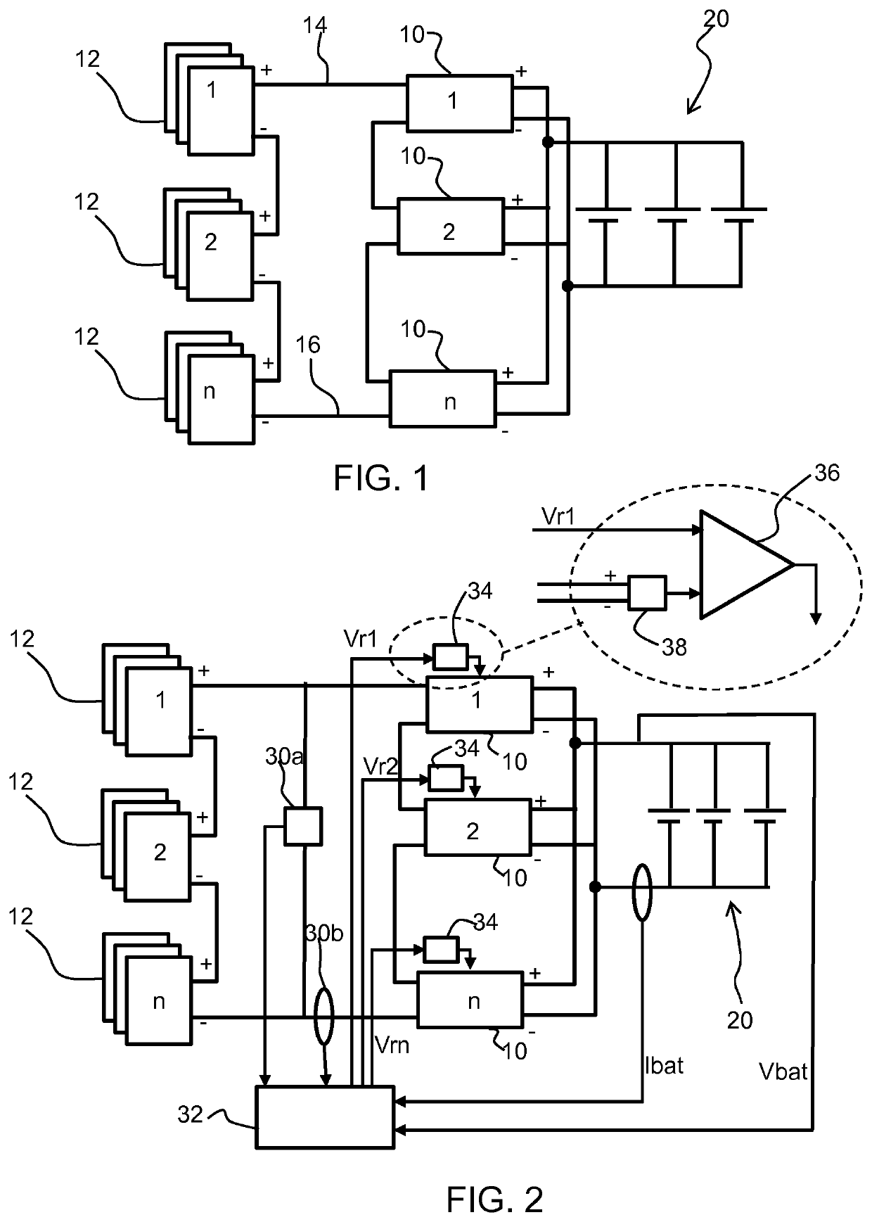
[0062]The invention provides a power conversion system to be used with an energy source, in which a plurality of conversion units are used in series via their input, with the energy source output. A master monitor unit is adapted to monitor the output power of the energy source, and to control the input voltage of each conversion unit synchronously in dependence on the monitored output power. In this way, a set of conversion units are configured, with the conversion units sharing the output from the energy source. This provides a scalable system.

[0063]FIG. 1 shows the general configuration of the system. The system comprises a set of conversion units 10 (shown as numbered 1 to n). Each conversion unit performs maximum power point tracking, although as explained below, each one may have a reduced functionality compared to a conventional full MPPT system. The system is connected to an energy source which is shown a set of solar panels 12 (each of which comprises a solar cell array of ...


PUM


Abstract

A power conversion system is to be used with an energy source. A plurality of conversion units are used in series via their output with the energy source output. A positive pin of a first converter and the negative pin of a last converter of the series are for connection to an output (14, 16) of the energy source, and for each two neighboring converters in this series a negative pin of an upstream converter is connected to a positive pin of a downstream converter which both pins are decoupled from the energy source except for the positive pin of the first converter and the negative pin of the last converter. A master monitor unit is adapted to monitor the output power of the energy source and to control the input voltage of each conversion unit synchronously in dependence on the monitored output power. In this way, a set of conversion units are configured, with the conversion units sharing the output from the energy source. This provides a scalable system.

Description

CROSS-REFERENCE TO PRIOR APPLICATIONS[0001]This application is the U.S. National Phase application under 35 U.S.C. § 371 of International Application No. PCT / EP2018 / 061070, filed on May 1, 2018, which claims the benefit of European Patent Application No. 17188962.9, filed on Sep. 1, 2017, and Indian Patent Application No. 201741015917, filed on May 5, 2017. These applications are hereby incorporated by reference herein.FIELD OF THE INVENTION[0002]This invention relates to power conversion systems and methods, and in particular to systems for converting power from a variable power source.BACKGROUND OF THE INVENTION[0003]Power conversion systems are used to collect energy from an energy source and to deliver the energy to a load or energy storage system. They are for example widely used for collecting energy from renewable energy sources.[0004]For example solar energy generation utilizing the rooftop areas of buildings is becoming increasingly popular around the world. In order to uti...

Claims


Application Information

Patent Timeline
Patent Type & Authority Patents(United States)
IPC IPC(8): H02J7/35G05F1/67G06F1/26H02J1/10H02J3/38H02M3/158H02M1/00
CPCH02J7/35G05F1/67G06F1/263H02J1/10H02J3/383H02M3/1584H02J2207/40H02M1/0074H02J2300/26H02J3/388
Inventor MAJI, GOUTAMMISHRA, PRIYA RANJAN
Owner SIGNIFY HLDG BV
Why Eureka
Try Eureka