Method for producing a rotor for an electric rotating machine

a technology of electric rotating machines and rotors, which is applied in the direction of dynamo-electric machines, magnetic circuit rotating parts, magnetic circuit shapes/forms/construction, etc., can solve the problem of significant restriction of the crystal grain of the conductor

Active Publication Date: 2022-08-09
SIEMENS AG
View PDF30 Cites 0 Cited by
  • Summary
  • Abstract
  • Description
  • Claims
  • Application Information

AI Technical Summary

Benefits of technology

The invention describes a method of optimizing the production of a rotor for an electric rotating machine using thermal spraying. This method involves spraying different metallic materials onto the shaft body of the machine to form a dense and tenacious coating that acts as a magnet pole-generating element. By using this method, the need for expensive and time-consuming processes such as hot isostatic pressing is reduced, resulting in simplified production and reduced manufacturing costs. The method also allows for the insulation of the metallic materials from one another, making it easier to produce rotors with specific configurations such as exciter windings.

Problems solved by technology

As a result, in the cover layer material the enlargement of the crystal grain of the conductor is restricted significantly, as a result of which conductive end rings are connected to the core and / or the conductive bars.

Method used


Image

  • Method for producing a rotor for an electric rotating machine
  • Method for producing a rotor for an electric rotating machine
  • Method for producing a rotor for an electric rotating machine

Examples


first embodiment

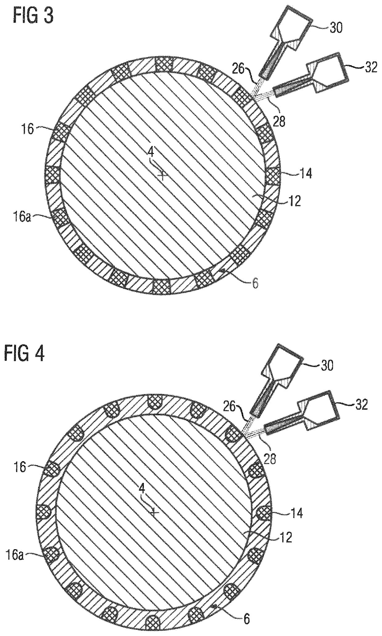
[0043]FIG. 3 shows a cross-section of a rotor 6 with a coating 14. The coating 14 comprises metallic solid body particles, which are sprayed by means of cold gas spraying onto the substantially cylindrical outer surface 24 of the shaft body 12. The coating comprises solid body particles made from a first metallic material 26 and solid body particles made from a second metallic material 28, wherein the first metallic material 26 and the second metallic material 28 are sprayed directly onto the substantially cylindrical outer surface 24 of the shaft body 12 with a first spraying device 28 and a second spraying device 32 in each instance. The squirrel cage 16 is, as in FIG. 2, formed from solid body particles of the first metallic material 28. The second metallic material 28, as in FIG. 2, is a soft-magnetic material, for instance steel, and corresponds substantially to the soft-magnetic material of the shaft body 12. The squirrel cage 16 is embedded completely into the rotor 6. At lea...

second embodiment

[0044]FIG. 4 shows a cross-section of a rotor 6 with a coating 14, wherein at least the short-circuit rods 16a of the squirrel cage 16 have a rounded contour cross-sectionally. By way of example, the contour of the short-circuit rods 16a are shown in a U shape. The squirrel cage 16 is embedded completely into the coating 14 of the rotor 6. The further embodiment of the rotor 6 in FIG. 4 corresponds to that in FIG. 3.

third embodiment

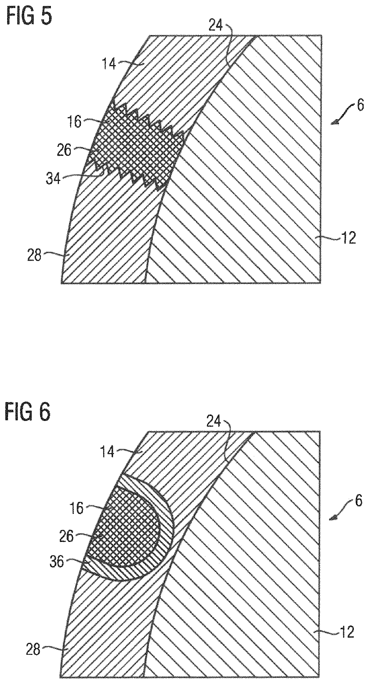
[0045]FIG. 5 shows an enlarged cross-section of a rotor 6 with a coating 14, wherein the first material 26 and the second material 28 are additionally connected in a form fit manner by a, for instance, sawtooth-shaped, rib structure 34. The squirrel cage 16 is embedded completely into the coating 14 of the rotor 6. The further embodiment of the rotor 6 in FIG. 5 corresponds to that in FIG. 3.


PUM


Abstract

A method for producing a rotor for an electric rotating machine includes spraying in a rolling manner a first metallic material and a second metallic material, which is different from the first metallic material, onto at least part of a substantially cylindrical outer surface of a shaft body by a thermal spraying method to form on the shaft body a coating which forms at least part of a squirrel cage.

Description

CROSS-REFERENCES TO RELATED APPLICATIONS[0001]This application is the U.S. National Stage of International Application No. PCT / EP2019 / 074803, filed Sep. 17, 2019, which designated the United States and has been published as International Publication No. WO 2020 / 084413 A1 and which claims the priority of European Patent Application, Serial No. 18197407.2, filed Sep. 28, 2018, pursuant to 35 U.S.C. 119(a)-(d).BACKGROUND OF THE INVENTION[0002]The invention further relates to a rotor for an electric rotating machine, which is produced with a method of this type.[0003]The invention furthermore relates to an electric rotating machine having at least one rotor of this type.[0004]A method of this type is used in particular to produce rotors of rapidly turning electric rotating machines, which are embodied as asynchronous machines, for instance. For instance, a rapidly turning electric rotating machine of this type can be operated with a power of at least 1 megawatt and a rotational speed of...

Claims


Application Information

Patent Timeline
IPC IPC(8): H02K15/00H02K15/12H02K17/16
CPCH02K15/0012H02K15/12H02K17/165H02K17/168H02K1/22
Inventor KÜMMLEE, HORSTSEIBICKE, FRANK
Owner SIEMENS AG
Why Eureka
Try Eureka