Sample measuring apparatus and sample measuring method

Active Publication Date: 2022-08-23
SYSMEX CORP
View PDF6 Cites 0 Cited by
  • Summary
  • Abstract
  • Description
  • Claims
  • Application Information

AI Technical Summary

Benefits of technology

[0007]In the sample measuring apparatus, the nozzle is lowered to suction the first liquid and the second liquid. The applicant has found that some of the liquids to be suctioned in the sample measuring apparatus have little influence on the measurement result of the measurement sample even if the liquid surface detection accuracy is not precise. Therefore, in the present aspect, the speed at which the nozzle is lowered is different with respect to a first liquid having a high influence on the measurement accuracy of the liquid surface detection and a second liquid having less influence on the measurement accuracy of the liquid surface detection than the first liquid. When the tip of the nozzle comes into contact with the liquid surface of the first liquid, the fluctuation of the liquid surface is slight and the tip of the nozzle is unlikely to vibrate due to the impact of the contact since the nozzle is lowered at the first speed that is slower than the second speed with respect to the second liquid. Therefore, the liquid surface of the first liquid can be accurately detected as compared with the second liquid, and since a precise amount of the first liquid is suctioned, the measurement of the measurement sample prepared by the first liquid is performed accurately. On the other hand, since the influence of the second liquid on the measurement of the measurement sample is slight, it is unnecessary to suction an accurate amount of the second liquid as compared with the first liquid and precise detection of the liquid surface is unnecessary. Therefore, it is possible to lower the nozzle at a high speed with respect to the second liquid.
[0054]According to the present invention, it is possible to perform accurate measurement while speeding up the measurement.

Problems solved by technology

On the other hand, since the influence of the second liquid on the measurement of the measurement sample is slight, it is unnecessary to suction an accurate amount of the second liquid as compared with the first liquid and precise detection of the liquid surface is unnecessary.

Method used


Image

  • Sample measuring apparatus and sample measuring method
  • Sample measuring apparatus and sample measuring method
  • Sample measuring apparatus and sample measuring method

Examples


Embodiment Construction

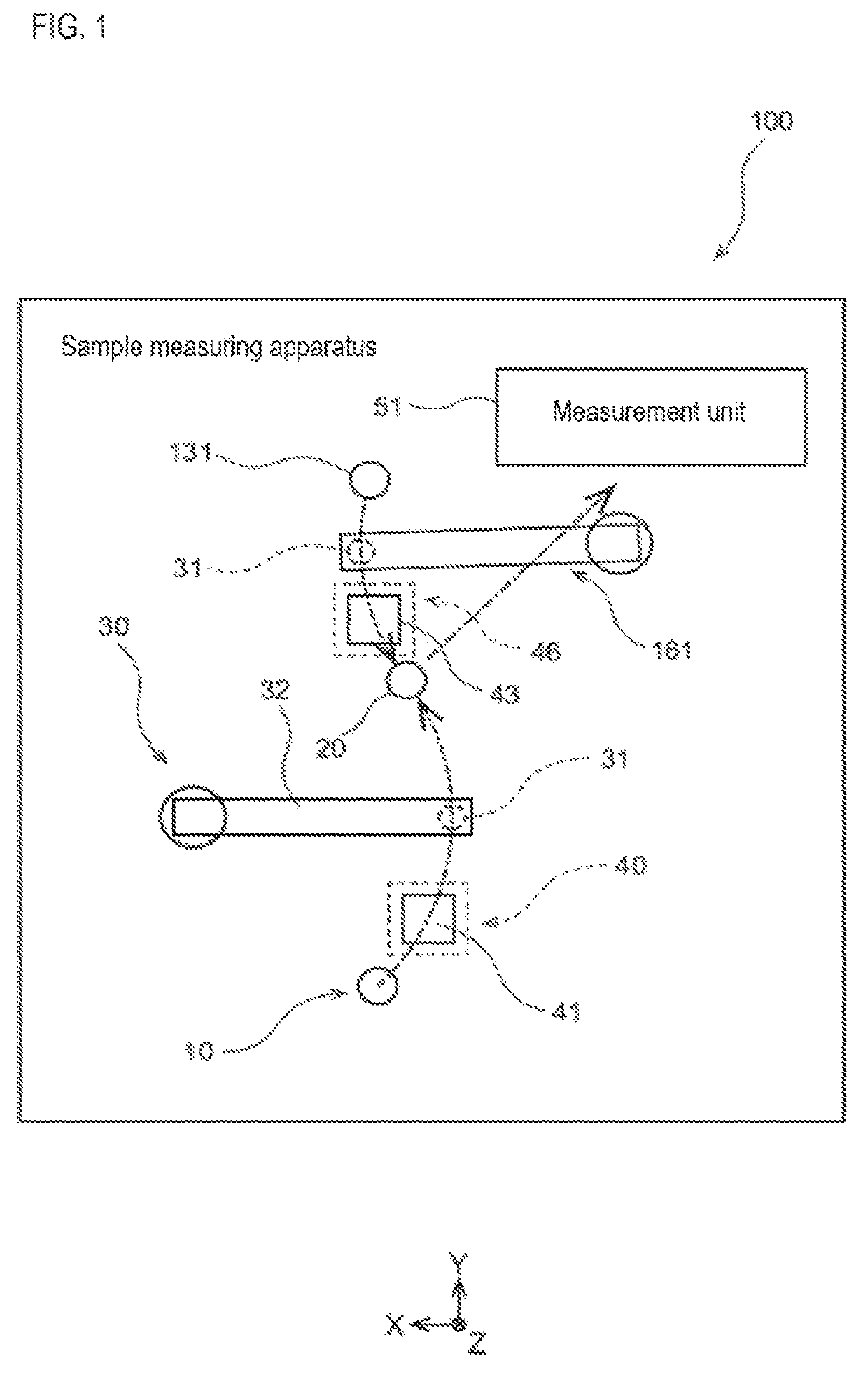
[0074]A sample measuring apparatus 100 and a sample measuring method according to an embodiment will be described with reference to FIGS. 1 to 18. In FIG. 1, the XYZ axes are orthogonal to each other, and the Z axis positive direction corresponds to the vertically downward direction. Note that the XYZ axes are set in the same manner in the other figures as in FIG. 1.

Structure of Sample Measuring Apparatus 100

[0075]A schematic configuration of the sample measuring apparatus 100 will be described with reference to FIG. 1. The sample measuring apparatus 100 measures the sample contained in the sample container 10. In one example, the sample measuring apparatus 100 is a blood coagulation measuring apparatus, the sample is whole blood or plasma, and the sample container 10 is a blood collection tube. The sample measuring apparatus 100 includes a sample dispensing mechanism 30, a reagent dispensing mechanism 161, cleaning mechanisms 40 and 46, and a measuring unit 51. The sample dispensin...


PUM

PropertyMeasurementUnit
speedaaaaaaaaaa
constant speedaaaaaaaaaa
surface heightaaaaaaaaaa

Abstract

The sample measuring apparatus includes a suction unit that includes a nozzle and a drive unit that raises and lowers the nozzle, and suctions a first liquid and a second liquid that is different from the first liquid; a liquid surface detecting unit that detects liquid surfaces of the first liquid and the second liquid; a control unit that controls the suction unit, and a measuring unit that measures a measurement sample prepared from the suctioned first liquid; wherein the control unit controls the suction unit to suction the first liquid and the second liquid based on the respective liquid surface detection result of the first liquid and the second liquid detected while lowering the nozzle, and a second speed at which the nozzle descends when detecting the liquid surface of the second liquid is faster than a first speed at which the nozzle descends when detecting the liquid surface of the first liquid.

Description

RELATED APPLICATIONS[0001]This application claims priority from prior Japanese Patent Application No. 2018-033636, filed on Feb. 27, 2018, entitled “Sample Measuring Apparatus and Sample Measuring Method”, the entire contents of which are incorporated herein by reference.BACKGROUND OF THE INVENTION1. Field of the Invention[0002]The present invention relates to a sample measuring apparatus and a sample measuring method for measuring a sample such as blood and the like.2. Description of the Related Art[0003]A sample measuring apparatus includes a working unit for suctioning a liquid via a nozzle from a container containing a liquid such as a sample or a reagent (see, for example, Japanese Patent Application Publication No. 2009-180605). In the sample measuring apparatus described in Japanese Patent Application No. 2009-180605, in order to suction a liquid such as a sample or a reagent, the switching height of the descending speed is set to be above the liquid surface height T1 of the ...

Claims


Application Information

Patent Timeline
Patent Type & Authority Patents(United States)
IPC IPC(8): G01N35/10G01N35/00
CPCG01N35/1011G01N35/0092G01N35/10G01N35/1004G01N2035/1006G01N2035/1025
Inventor YAMATO, TAKASHIINAGAKI, JUNSAITO, SHUNSUKENAKAMURA, YOSHINORI
Owner SYSMEX CORP
Why Eureka
Try Eureka