
Implant for bone

a technology for implants and bones, applied in the field of implants for bones, can solve the problems of increasing the screw length for osteoporotic bones, rarely providing satisfactory resistance to the fixation screw, and reducing the possibility of injury to nearby structures such as arteries, veins and nervous tissues

Active Publication Date: 2022-09-06
BLUE SKY TECHNOLOGIES LLC
View PDF30 Cites 1 Cited by
  • Summary
  • Abstract
  • Description
  • Claims
  • Application Information

AI Technical Summary

Benefits of technology

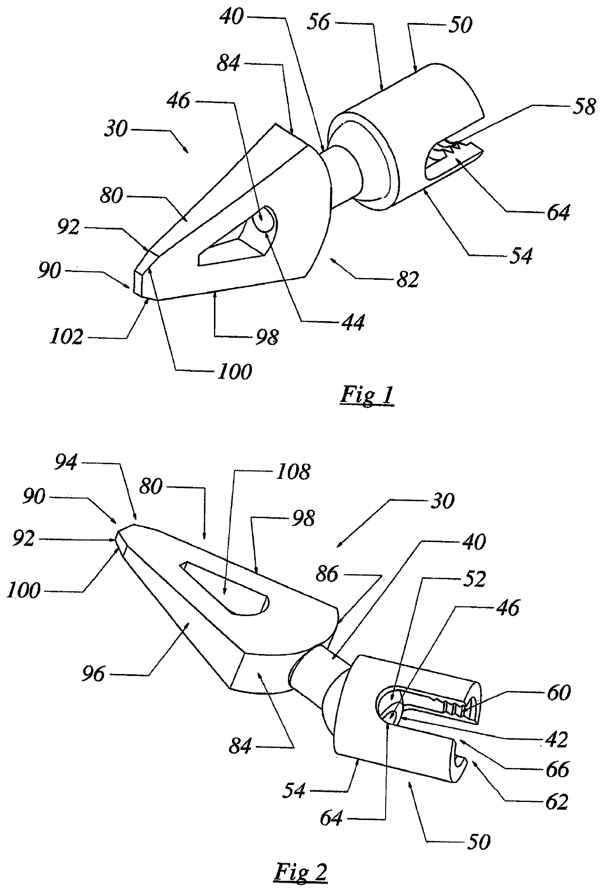
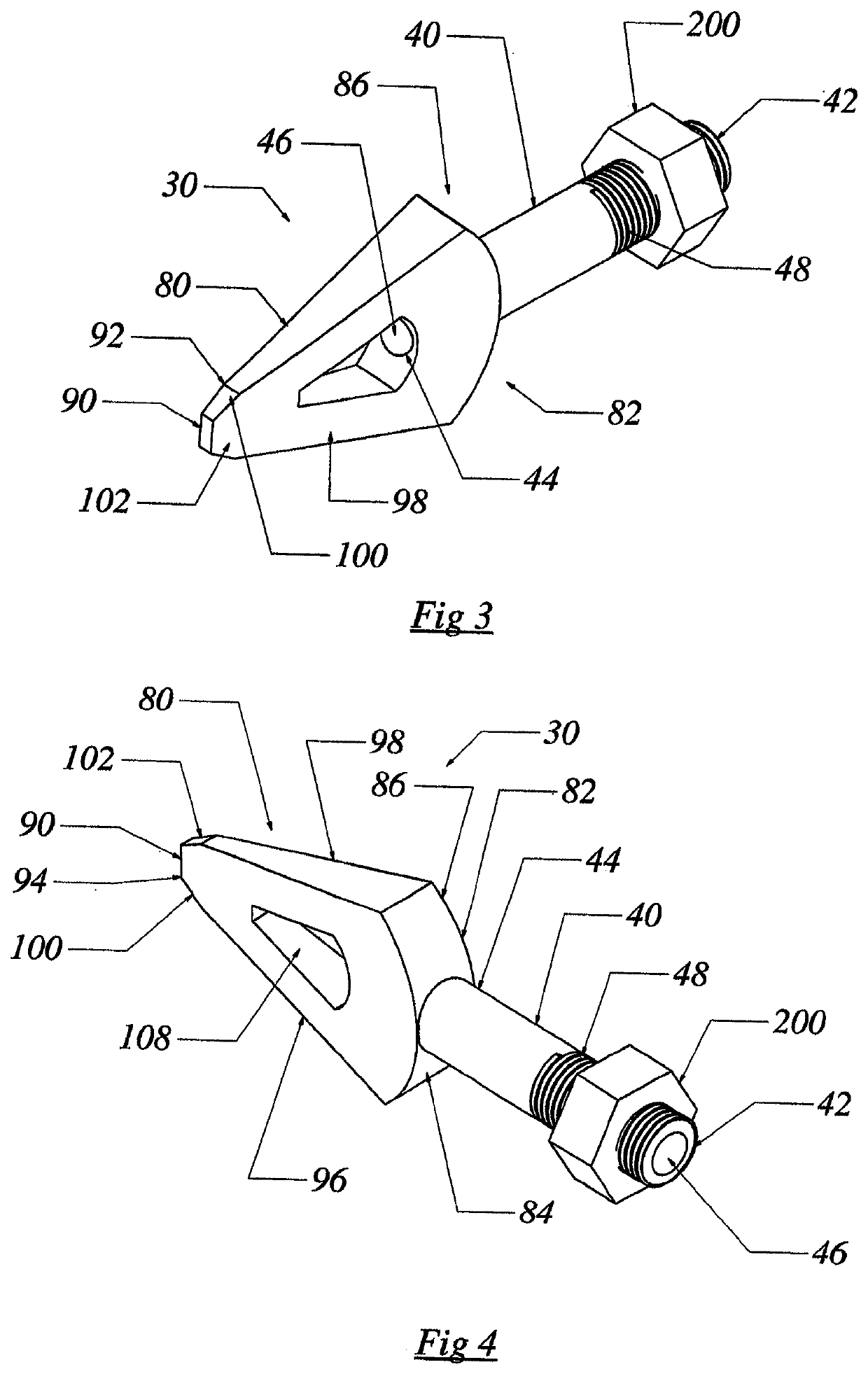
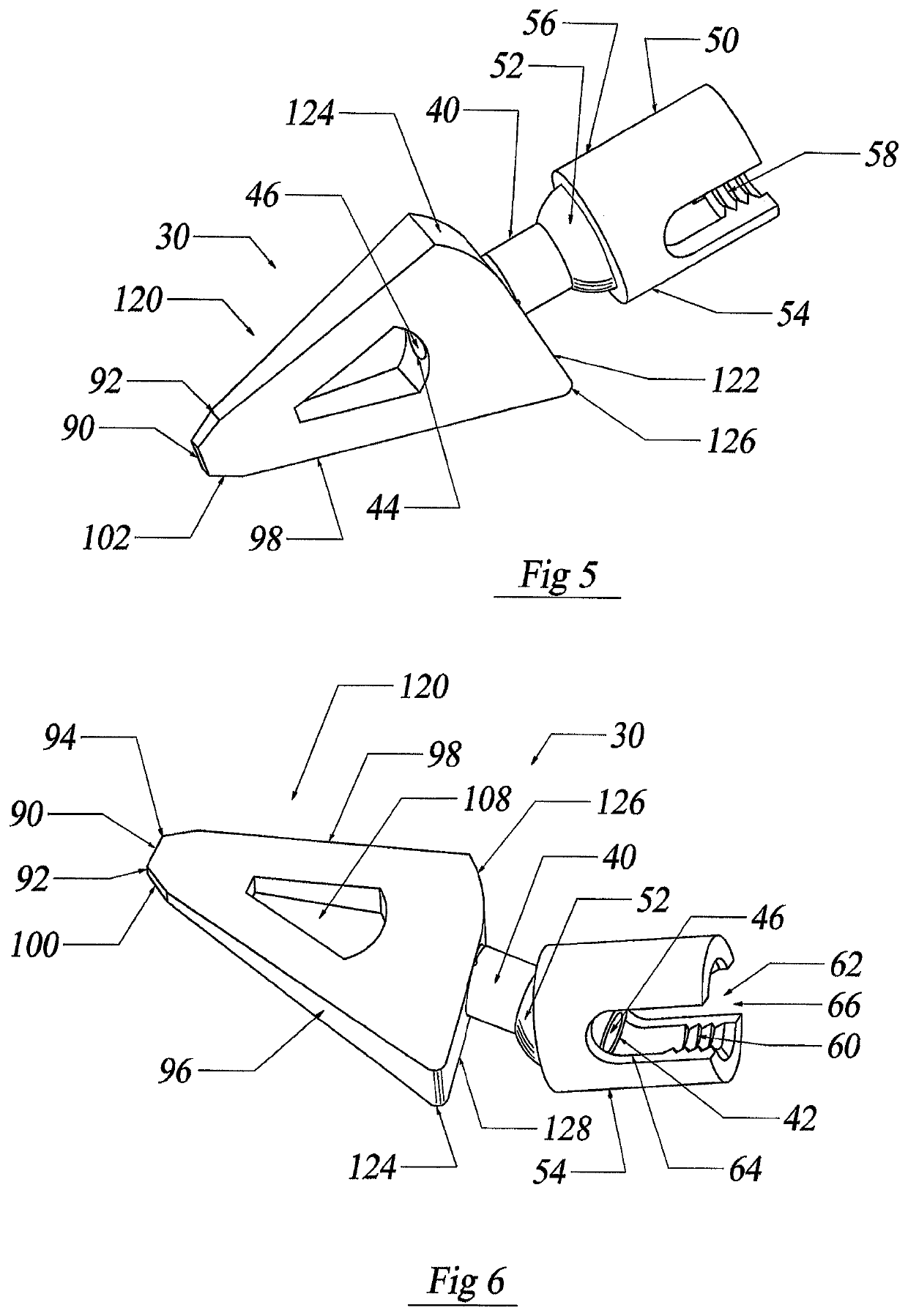
[0005]The present invention provides a biocompatible implant for bone that can be interlocked with a device distinct from the implant. The current implant is also provided with a blade for cutting tissue. Preferred embodiments of the current fastener can also be utilized for transporting biocompatible devices / substances, such as adhesives, cameras, cannulas, fiber optics, implants, pharmaceuticals, etc. Preferred embodiments of the implant's blade are provided with an aperture. The aperture can assist tissue growth, such as bone, into and through the implant as well onto the inward surfaces of the implant. Select embodiments of the implant are provided with surface treatments in anticipation of improving attachment of bone to the implant.
[0006]With regard to spinal surgical procedures, prior art traditional fixation screws fixation stability is dependent on the healthy composition of the cancellous bone. Those skilled in the art recognize the healthy cortical bone is from about 20 to about 100 times stronger than healthy cancelleous bone. Those skilled in the art also know that increasing the screw length for osteoporotic bone rarely provides satisfactory resistance against the fixation screw from pulling-out or backing-out of bone. The blade of the current implant is shorter and wider than traditional fixation screws. Because of its novel structure and surgical insertion technique, the present implant has greater resistance against pulling-out or backing-out of osteoporotic bone. Further still, the blade's shorter length reduces the possibility of injury to nearby structures such as arteries, veins and nervous tissues. It is believed that the current invention's resistance to pull-out or back-out improves implant-construct stability, higher bone fusion rates and better postoperative clinical outcomes than prior art fixation screws.
[0007]For surgical procedures involving bone, the current implant can be inserted through a small linear aperture into the bone tissue. In one of the preferred uses of the current implant, subsequent to blade's surgical insertion into bone, the blade can be rotated up to 90 degrees relative to the plane of the surgical incision. Among other things, rotation of the blade increases resistance against pull-out or back-out of the blade from bone when compared to prior art fixation screws. It is also believed that the width of the implant's blade can contact a greater surface area of healthier cortical bone distinct from the surgically created cavity, thereby improving the possibility of successful postoperative bone fusion relative to prior art fixation screws.
[0014]It is still another aspect of the present invention to provide an implant that improves resistance to pull-out or back-out and improves implant-construct stability, higher bone fusion rates and better postoperative clinical outcomes than prior art fixation screws.
[0015]Yet still another aspect of the present invention is to provide an implant with greater resistance against pulling-out or backing-out of osteoporotic bone that current fixation screws.

Problems solved by technology

Those skilled in the art also know that increasing the screw length for osteoporotic bone rarely provides satisfactory resistance against the fixation screw from pulling-out or backing-out of bone.
Further still, the blade's shorter length reduces the possibility of injury to nearby structures such as arteries, veins and nervous tissues.

Method used


Image

  • Implant for bone
  • Implant for bone
  • Implant for bone

Examples


Embodiment Construction

[0044]Although the disclosure hereof is detailed to enable those skilled in the art to practice the invention, the embodiments published herein merely exemplify the present invention.

[0045]In the most general sense, the present invention is an implant for bone where the implant is adapted for connection with a device distinct from the implant. Among other things, the current invention can be adapted for use with vertebra or other bone tissues. The present implant is particularly adapted for use in the cervical region of the spine. The current invention can be provided with a conduit for transporting biocompatible devices / substances or chemotherapeutic agents, such as adhesives, cameras, cannulas, fiber optics, implants, pharmaceuticals, etc. Dispersion of adhesives from the windows or openings of the implant before closing the surgical wound, reduces the risk of the fastener backing out of the wound prior to the fastener fully interlocking with tissue overgrowth. Polymethymethacryla...


PUM


Abstract

The present invention is an implant for bone. The current implant is particularly useful in spinal surgical procedures.

Description

PRIORITY[0001]Applicant claims priority to U.S. application Ser. No. 16 / 648,518—Implant for Bone—filed Mar. 18, 2020, that claims priority to PCT / US2019 / 054383—Implant for Bone—, filed Oct. 3, 2019 that claims the benefit of U.S. Provisional Application No. 62 / 809,670—Implant for Bone—filed on Feb. 24, 2019.BACKGROUND OF THE INVENTIONA. Field of the Invention[0002]Among other things, the present invention is an implant for bone. The current implant is particularly suited for implantation into mammalian spinal tissues. The present implant is provided with a cutting blade. Select embodiments of the current invention include surface treatments in anticipation of improving attachment of bone to the implant.B. Description of the Previous Art[0003]Any discussion of references cited in this Description of the Previous Art merely summarizes the disclosures of the cited references and Applicant makes no admission that any cited reference or portion thereof is relevant prior art. Applicant re...

Claims


Application Information

Patent Timeline
Patent Type & Authority Patents(United States)
IPC IPC(8): A61B17/70A61B17/16
CPCA61B17/1671A61B17/70A61B17/7035A61B17/84A61B17/1604
Inventor CASTRO, FRANK
Owner BLUE SKY TECHNOLOGIES LLC
Learn More