Method and apparatus for analysing particulate material

a technology of particulate material and method, applied in the direction of sampling, instruments, measurement devices, etc., can solve the problems of inability to accurately analyse the results, affect limit the usefulness of the results for certain applications,

Active Publication Date: 2022-09-06
FCT - ACTECH
View PDF15 Cites 0 Cited by
  • Summary
  • Abstract
  • Description
  • Claims
  • Application Information

AI Technical Summary

Benefits of technology

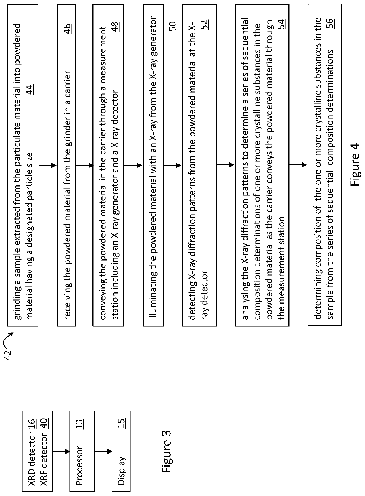
[0011]In an embodiment, the grinder allows relatively coarse particulate material (e.g. up to 14 mm diameter) to be ground into a sufficiently fine powder for the apparatus to analyse the material. The grinder enables the removal of several steps of user interaction with the sample that are described above (e.g. fine grinding and preparing the powdered sample) with respect to the prior art example of a spectral analyser; thereby increasing precision and accuracy of the apparatus. For example, the designated particle size from the grinder has 30% of particles less than 45 μm. The coarser particle size from the grinder, than say the prior art example of 5 μm, is enabled by the carrier conveying a much larger volume of powdered material through the measuring station to determine a series of composition determinations of the powdered material rather than just determining a composition determination of a small static volume of powdered material. In the example, the volume of the powdered material in the above mentioned prior art example is ˜1 cm3 and the volume of powdered material conveyed through the measuring station is ˜150 cm3.
[0014]In an embodiment, the processor is configured to receive the X-ray diffraction pattern of the standard material and compare the diffraction pattern of the standard material with an expected diffraction pattern of the standard material to determine a scale factor corresponding to at least in part a flux value of the X-ray generator. The processor is then configured to apply the scale factor to the series of sequential composition determinations of crystalline substances to determine a calibrated composition of the one or more crystalline substances in the sample. It will be appreciated by those persons skilled in the art that X-ray tubes reduce their flux with operational time due to various factors such as tungsten deposition, loss of vacuum, environmental temperature or partial filament failure. This flux can be correlated with the scale factor from the determined and the expected patterns, and is used as compensation for the tube flux variation over time to calibrate and maintain accuracy of the apparatus. Thus, by applying the scale factor, the accuracy of the composition determinations by XRD of the one or more crystalline substances in the sample is improved.
[0020]In an embodiment, the plate is disposed on an actuator configured to move the standard material on the plate between a first position in the measurement station and a second positon not in the measurement station. The actuator is further configured to move the standard material into the measurement station before and / or after the carrier conveys the powdered material through the measurement station. That is, in this embodiment, the scale factor is determined with each determination of the composition of crystalline substances in the sample, to compensate for the X-ray source flux to improve the quality of the analysis.
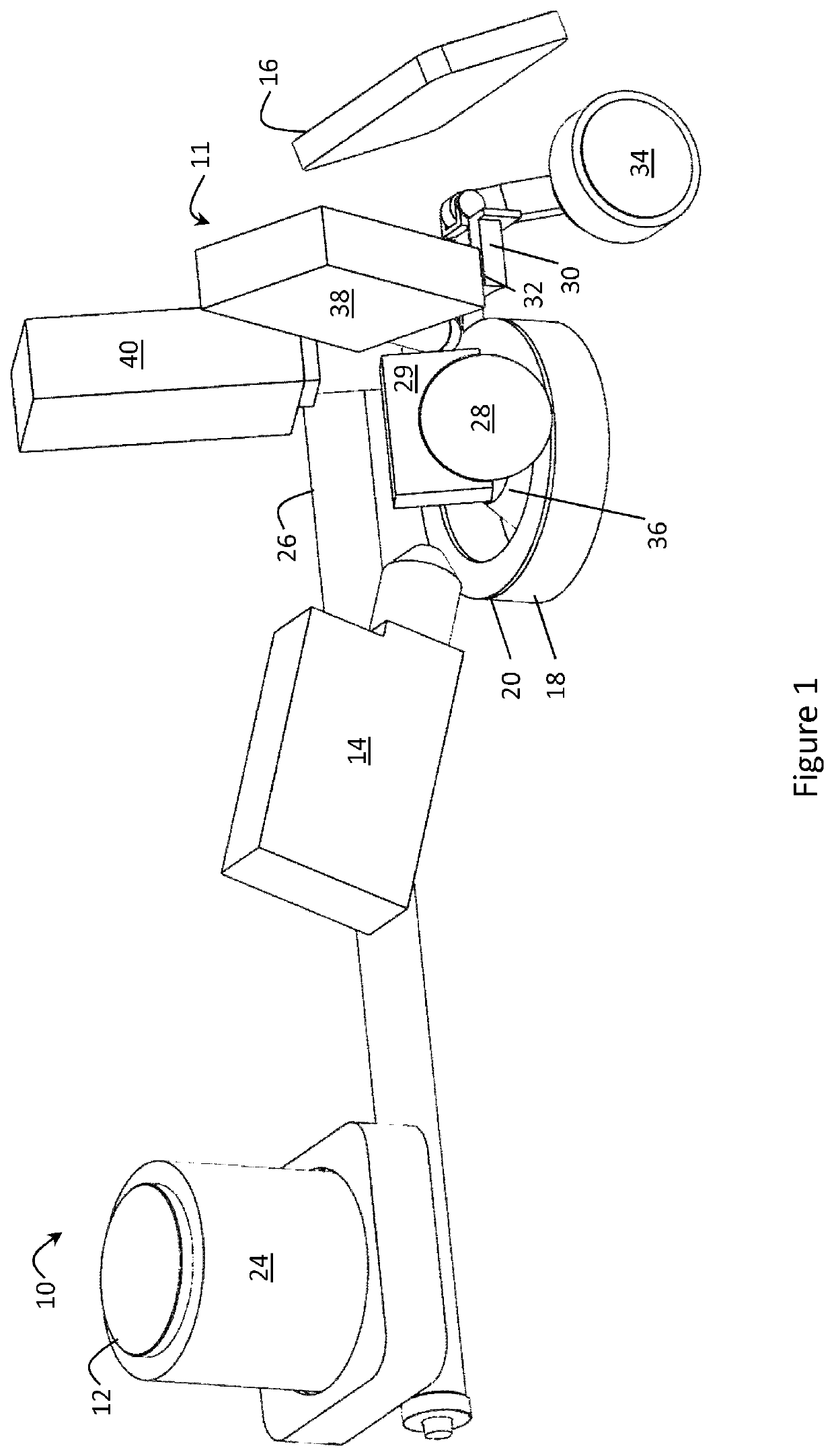
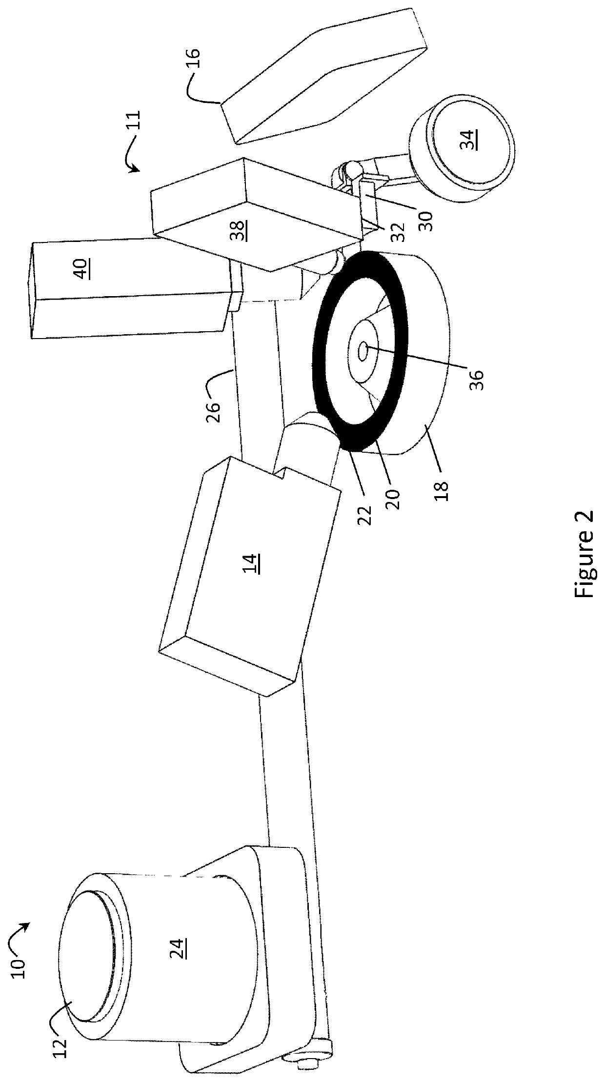
[0023]Preferably, the roller includes a heating element to heat the roller to a designated temperature. The heating of the roller ensures that ‘sticky’ powdered material does not become a problem by attaching itself to the roller. If small amounts of material do attach to the roller it would result in an uneven or patchy upper surface of the powdered material in the groove, providing a poor bed for analysis and inaccurate results. The heating element enables the roller to be heated to a material dependent temperature. For example, for cement product, this temperature is around 90° C. The heated roller is speed matched to the speed of rotation of the turntable and the taper allows for no speed differential between the inner and outer tracks of the groove; thus providing a very smooth and flat surface of powdered material to be presented to the X-ray beam. In a further embodiment, the roller is curved to impart a slight curvature to the sample bed in the groove which aids in focusing the X-ray beams for XRD.
[0024]As mentioned, the rotating turntable is used to significantly increase the volume of sample that is being analysed from the above mentioned prior art static sample analyser. Hence, the number of diffraction conditions that are going to be experienced by particles in the sample is also increased. The traditional XRD systems described above use a sample plate with around 1 cm3 of material and rely heavily on sample preparation to achieve reliable results. The apparatus, however, uses a much larger sample volume of around 150 times, which provides significant advantage such as better sample representation, greater number of diffraction conditions and less single particle effects which are averaged out over a large number of analysed X-ray diffraction patterns. By using a larger volume of powdered sample material for analysis, there is a much higher number of crystallites that line up in the X-ray beam producing diffracted beams, as per Braggs's Law (2d sin θ=nλ). The higher number of detected diffracted beams allow for a significant reduction (e.g. 10×) in X-ray power requirements and the relaxation of the requirement for a very fine particle size.
[0033]In another embodiment, the apparatus is arranged to improve results of the analysis of the material by reducing instances of the detector detecting scattered X-ray beams from the sample and the standard material, by using an anti-scatter disc disposed at the centre of the turntable.

Problems solved by technology

This further sample preparation has many drawbacks as it is time intensive and it limits the usefulness of results for certain applications, such as process control.
Furthermore, the fine grinding required of the sample can cause changes in the material affecting the analysis.
This stream of sample flow, however, can contain particulates having a relatively large distribution of particle sizes, which may not be accurately analysed, and the moving stream may not be presented as a uniform flat bed for analysis due to, for example, the material being “sticky”.
In addition, the sample flow typically contains non-crystalline substances (i.e. poorly crystalline and / or amorphous substances), such as glassy compounds or slag, fly-ash, and pozzolans, which can affect the accuracy of the analysis.

Method used


Image

  • Method and apparatus for analysing particulate material
  • Method and apparatus for analysing particulate material
  • Method and apparatus for analysing particulate material

Examples


Embodiment Construction

[0041]According to an embodiment there is provided an apparatus 10 for analysing particulate material having crystalline substances as shown in FIG. 1. The material to be analysed is extracted from particulate material in the form of, for example, cement product from a cement mill or cement clinker from a kiln. The material to be analysed is in dry powder form and, as mentioned above, could alternatively be an ore, a mineral process intermediary or residue, etc. In the embodiment, the particulate material also has amorphous and poorly crystalline substances, such as one or more of opaline silica, iron oxy hydroxides, components in fly ash and blast-furnace slag.

[0042]In use of the apparatus 10 shown in the Figures, a user extracts a sample of particulate material be analysed, from say a stream of cement clinker particulate, and provides it to a grinder 12 of the apparatus 10. The grinder 12 receives the sample and grinds it into a powdered material having a designated particle size....


PUM

PropertyMeasurementUnit
particle sizeaaaaaaaaaa
diameteraaaaaaaaaa
particle sizeaaaaaaaaaa

Abstract

A method and apparatus for analysing particulate material having one or more crystalline substances, the apparatus including: a grinder for receiving a sample extracted from the particulate material and grinding the sample into powdered material having a designated particle size; a measurement station including an X-ray generator for illuminating the powdered material with an X-ray beam and an X-ray detector for detecting X-ray diffraction patterns from the powdered material; a carrier for receiving the powdered material from the grinder and conveying the powdered material through the measurement station; and a processor configured to: receive the X-ray diffraction patterns of the powdered material from the X-ray detector; analyse the X-ray diffraction patterns to determine a series of sequential composition determinations of one or more crystalline substances in the powdered material as the carrier conveys the powdered material through the measurement station; and determine composition of the one or more crystalline substances in the sample from the series of sequential composition determinations.

Description

FIELD OF THE INVENTION[0001]The present invention relates to a method and apparatus for analysing particulate material having one or more crystalline substances. The present invention particularly, but not exclusively, relates to determining composition of one or more crystalline substances in a cement or ore sample by X-ray diffraction. The present invention further, but not exclusively, relates to determining elemental composition of substances in the cement or ore sample by X-ray fluorescence.BACKGROUND OF THE INVENTION[0002]Existing analysers of particulate material generally employ either destructive techniques, such as chemical analysis, or non-destructive techniques, such as spectral analysis, to analyse the mineralogy of a sample of the material. Spectral analysers typically require that a sample is obtained and prepared for the spectral analysis by grinding the sample and forming individual sample pellets of the order of a few grams for presentation to the analyser for anal...

Claims


Application Information

Patent Timeline
Patent Type & Authority Patents(United States)
IPC IPC(8): G01N23/207G01N1/28G01N23/223
CPCG01N23/207G01N1/286G01N23/223G01N2001/2866G01N2223/076
Inventor STORER, PETER J.ABSALOM, NICK P.RAPSON, DAVID S.IANCU, BOGDAN A.MARSCHALL, SIMON G.
Owner FCT - ACTECH
Why Eureka
Try Eureka