Cooling plate for controlling the temperature of at least one battery cell, and battery system

a technology for controlling the temperature of at least one battery cell and battery system, which is applied in the direction of batteries, cell components, lighting and heating apparatus, etc., and can solve problems such as not allowing good tolerance equalization

Active Publication Date: 2022-09-06
ROBERT BOSCH GMBH
View PDF6 Cites 2 Cited by
  • Summary
  • Abstract
  • Description
  • Claims
  • Application Information

AI Technical Summary

Benefits of technology

[0003]The present invention describes a cooling plate for controlling the temperature of at least one battery cell, in particular for a traction battery. The cooling plate has a frame, which forms a flow chamber for a coolant to flow through, and a cover of flexible design. The cover of flexible design delimits the flow chamber in an at least partially fluid-tight manner and is provided for making thermal contact with the at least one battery cell. According to the invention, the cooling plate has at least one supporting element, which is arranged within the flow chamber and around which coolant can flow, for increasing the turbulence in the coolant flowing through the flow chamber and for supporting the at least one battery cell, which supporting element makes mechanical contact with the cover of flexible design.
[0004]This has the advantage that a cooling capacity or temperature control capacity which is improved compared to the prior art can be provided, so that reliable temperature control of the at least one battery cell is possible. In this case, the increase in turbulence which can be formed by means of the supporting element serves to thoroughly mix the coolant more intensively. In particular, a laminar flow which is formed within the flow chamber by the coolant, in particular a separating flow which is formed along a longitudinal direction of the cooling plate, is disturbed in such a manner that a temperature gradient perpendicular and / or parallel in relation to the longitudinal direction is minimized. For example, the supporting element has the effect of forming a turbulent flow with a formation of vortices in the coolant. For example, the supporting element preferably creates a flow with a Reynolds number exceeding 100, advantageously exceeding 1000, particularly advantageously exceeding 2000.
[0005]In addition, the cooling capacity or temperature control capacity is further improved since the supporting elements allow, in particular, thermal contact to be made with the battery cell in an improved manner in comparison to the prior art. Owing to an internal pressure which is generated within the cooling plate by the coolant flowing through the flow chamber, the cover of flexible design can be expanded or inflated at least in regions toward the outside. Regions of this kind of a cover of flexible design which is expanded or inflated toward the outside allow equalization of unevennesses on a surface of the battery cell which is provided for making thermal contact. Webs, which are formed along the longitudinal direction, for forming flow ducts are customary in the prior art, which webs are used for fastening the cover of flexible design. Cooling plates of this kind have regions which are expanded along the webs and in which the cover of flexible design cannot be expanded or inflated toward the outside by the internal pressure and therefore does not allow good tolerance equalization. The present invention is, in particular, an improvement over a prior art of this kind since, on account of the use of supporting elements around which fluid can flow, a surface of the cover of flexible design, which surface cannot be expanded or inflated toward the outside, is minimized for example, in particular is severely reduced in comparison to the prior art. Tolerance equalization is advantageously possible over largely an entire surface of the cover of flexible design.

Problems solved by technology

Cooling plates of this kind have regions which are expanded along the webs and in which the cover of flexible design cannot be expanded or inflated toward the outside by the internal pressure and therefore does not allow good tolerance equalization.

Method used


Image

  • Cooling plate for controlling the temperature of at least one battery cell, and battery system
  • Cooling plate for controlling the temperature of at least one battery cell, and battery system
  • Cooling plate for controlling the temperature of at least one battery cell, and battery system

Examples


Embodiment Construction

[0037]Identical parts are provided with the same reference numerals in the various design variants.

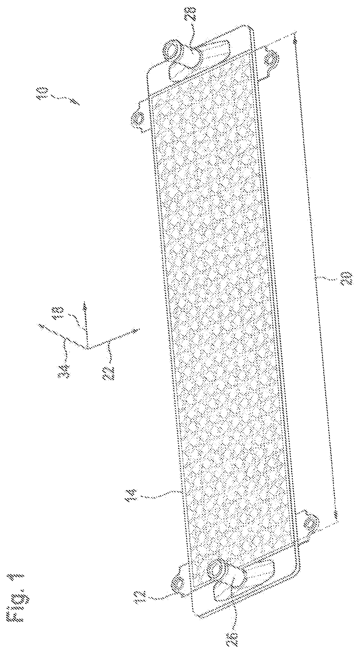
[0038]FIG. 1 shows a perspective view of an embodiment according to the invention of a cooling plate 10 for controlling the temperature of at least one battery cell.

[0039]The cooling plate 10 has a frame 12. In the exemplary embodiment shown according to FIG. 1, the frame is formed from plastic. The cooling plate 10 has a cover 14 of flexible design. The frame 12 has a flow chamber 16. The flow chamber 16 is covered or overlaid by the cover 14 of flexible design. In particular, the flow chamber 16 is closed off from an external environment by the cover 14 of flexible design.

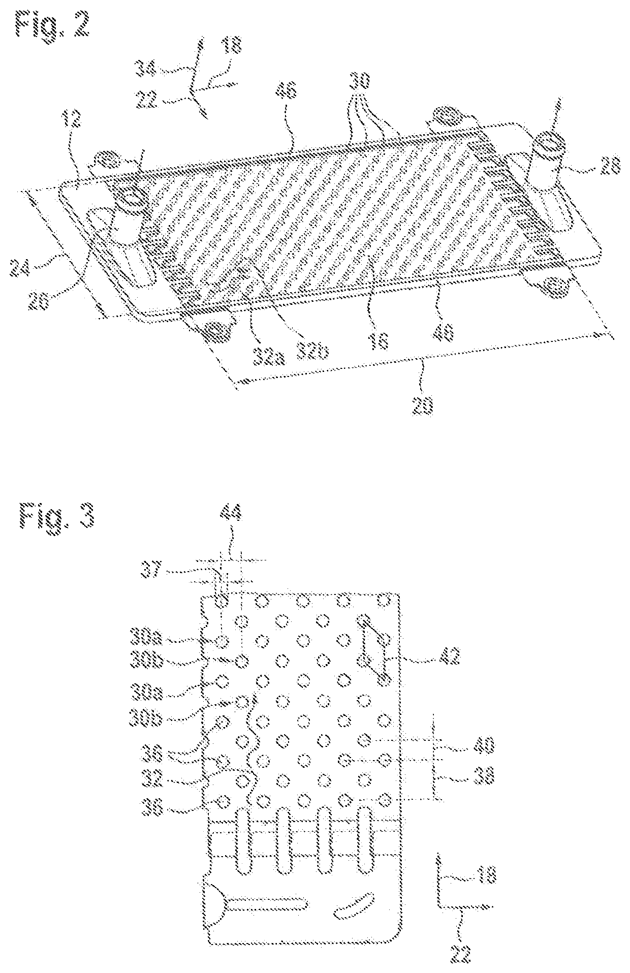
[0040]FIG. 2 shows a perspective view of the frame 12 without the cover 14 of flexible design for the purpose of illustrating the flow chamber 16. Here, the flow chamber 16 has, in a longitudinal direction 18, a flow chamber length 20 of 40 cm for example. In alternative embodiments, the value of the flow chamber le...


PUM

PropertyMeasurementUnit
Reynolds numberaaaaaaaaaa
angleaaaaaaaaaa

Abstract

A cooling plate (10) for controlling the temperature of at least one battery cell, in particular for a traction battery, having a frame (12), which forms a flow chamber (16) for a coolant to flow through, and a cover (14) of flexible design which delimits the flow chamber (16) in an at least partially fluid-tight manner and is provided for making thermal contact with the at least one battery cell. It is proposed that the cooling plate (10) has at least one supporting element (30), which is arranged within the flow chamber (16) and around which coolant can flow, for increasing the turbulence in the coolant flowing through the flow chamber (16) and for supporting the at least one battery cell, which supporting element makes mechanical contact with the cover (14) of flexible design.

Description

BACKGROUND OF THE INVENTION[0001]The invention relates to a cooling plate for controlling the temperature of at least one battery cell. Furthermore, the invention also relates to a battery system comprising a cooling plate of this kind.[0002]EP0516280A1 discloses cooling plates for controlling the temperature of traction battery cells which have flow ducts which are covered by a flexible cover for making thermal contact with the traction battery. Cooling plates of this kind have the disadvantage that reliable temperature control of the traction battery cells is not always possible.SUMMARY OF THE INVENTION[0003]The present invention describes a cooling plate for controlling the temperature of at least one battery cell, in particular for a traction battery. The cooling plate has a frame, which forms a flow chamber for a coolant to flow through, and a cover of flexible design. The cover of flexible design delimits the flow chamber in an at least partially fluid-tight manner and is prov...

Claims


Application Information

Patent Timeline
Patent Type & Authority Patents(United States)
IPC IPC(8): H01M10/6554F28F13/12H01M10/6556H01M10/6568H01M10/613H01M50/20H01M50/204
CPCH01M10/6554F28F13/12H01M10/613H01M10/6556H01M10/6568H01M10/6551H01M50/204F28F3/12F28F3/04H01M10/625H01M10/653H01M10/6561H01M10/6567H01M2220/20Y02E60/10
Inventor SCHMITT, MARKUSRUEHLE, ANDREASKOPP, BENJAMIN
Owner ROBERT BOSCH GMBH
Why Eureka
Try Eureka