
CMC component including directionally controllable CMC insert and method of fabrication

a technology of direction control and insert, which is applied in the direction of machines/engines, stators, light and heating equipment, etc., can solve the problems of pre-planned replacement, and achieve the effect of low crack growth driving force and high stress region of turbomachine components

Active Publication Date: 2022-10-04
GENERAL ELECTRIC CO
View PDF27 Cites 2 Cited by
  • Summary
  • Abstract
  • Description
  • Claims
  • Application Information

AI Technical Summary

Benefits of technology

The patent describes a ceramic matrix composite component with a special insert that can be directed to strengthen areas of high stress. The insert is shaped and placed within the layers of the composite to redirect cracks towards a region of low crack growth, increasing the overall strength of the component. This design can be used in turbomachines to improve their durability and performance.

Problems solved by technology

During normal use in such high-temperature applications, or when operating the CMC components above their proportional limit, defects, in the form of cracks, may develop in high stress / strain regions and premature replacement is likely.

Method used


Image

  • CMC component including directionally controllable CMC insert and method of fabrication
  • CMC component including directionally controllable CMC insert and method of fabrication
  • CMC component including directionally controllable CMC insert and method of fabrication

Examples


Embodiment Construction

[0026]Reference now will be made in detail to embodiments of the disclosure, one or more examples of which are illustrated in the drawings. Each example is provided by way of explanation of the disclosure, not limitation of the disclosure. In fact, it will be apparent to those skilled in the art that various modifications and variations can be made in the present disclosure without departing from the scope or spirit of the disclosure. For instance, features illustrated or described as part of one embodiment can be used with another embodiment to yield a still further embodiment. Thus, it is intended that the present disclosure covers such modifications and variations as come within the scope of the appended claims and their equivalents.

[0027]The terminology used herein is for the purpose of describing particular embodiments only and is not intended to be limiting of the disclosure. As used herein, the singular forms “a”, “an” and “the” are intended to include the plural forms as wel...


PUM

PropertyMeasurementUnit
angleaaaaaaaaaa
anglesaaaaaaaaaa
anglesaaaaaaaaaa

Abstract

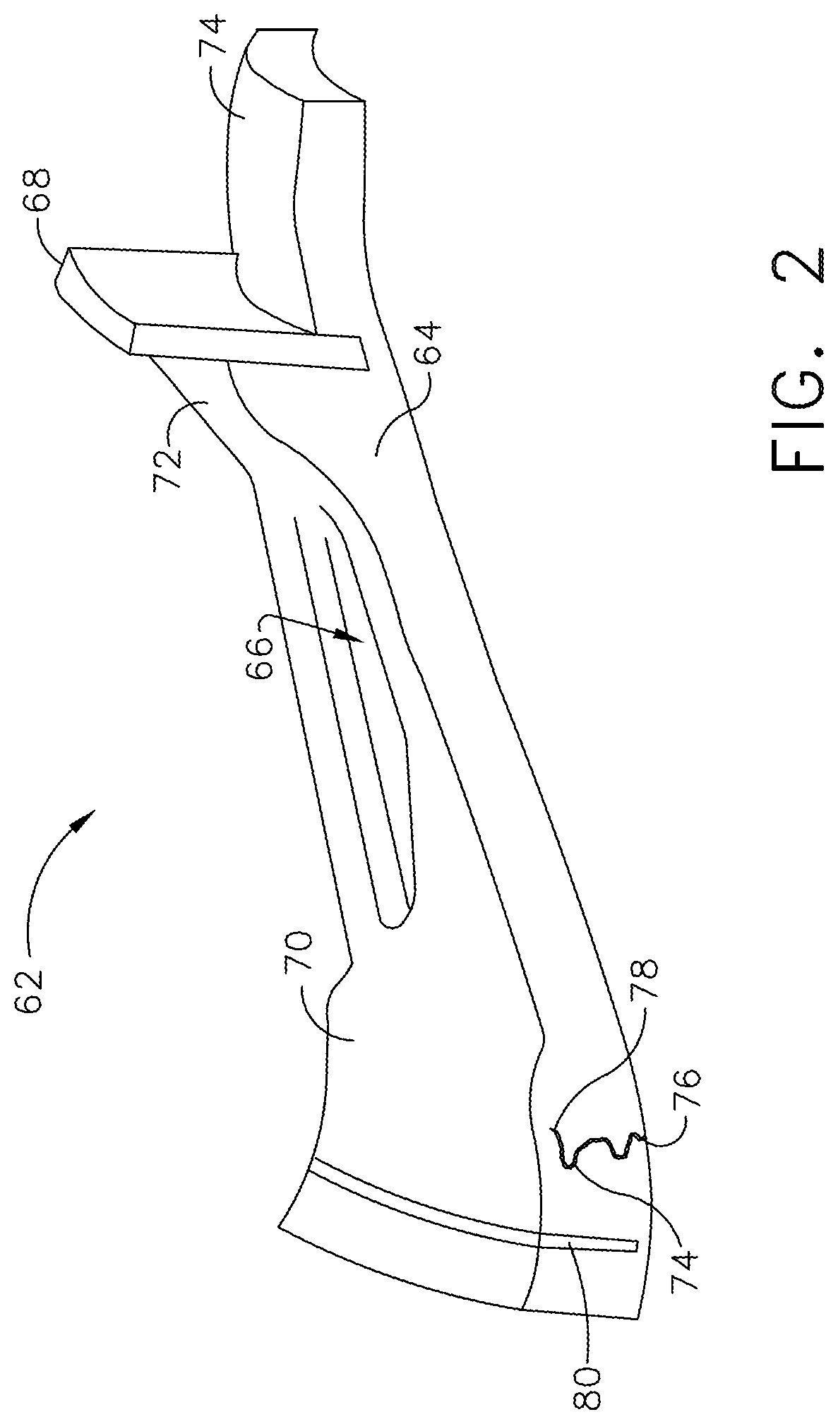
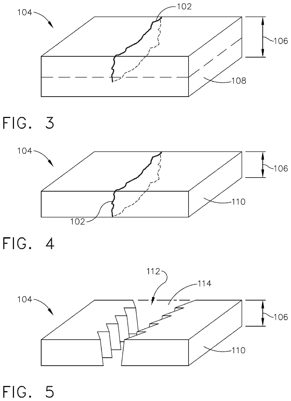
A ceramic matrix composite (CMC) component including a plurality of layers of a CMC and a directionally controllable CMC insert. The directionally controllable CMC insert is disposed in the plurality of layers of a ceramic matrix composite. The directionally controllable CMC insert includes an optimized architecture to strengthen a high stress region of the CMC component. The directionally controllable CMC insert is geometrically configured and disposed within the plurality of layers of the CMC to redirect a crack in the CMC component toward a region of low crack growth driving force. A turbomachine and method of forming a turbomachine member including a plurality of layers of a CMC and having the directionally controllable CMC insert disposed in a shaped void are additionally disclosed.

Description

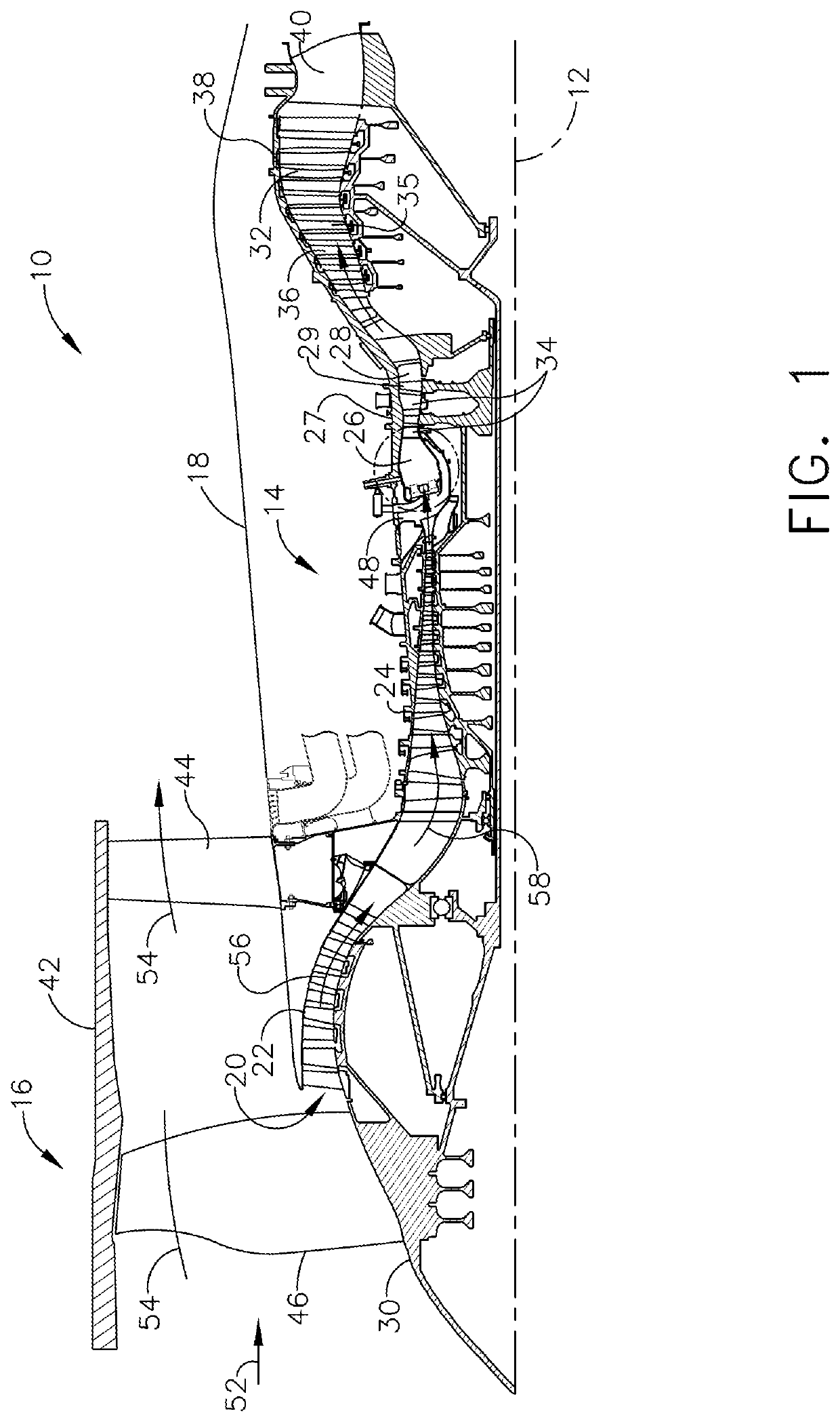
BACKGROUND[0001]The subject matter disclosed herein relates to ceramic matrix composite (CMC) components and the manufacture or repair of such components. More particularly, this disclosure is directed to CMC inserts for use in controlling cracks in CMC components and a method of controlling cracks formed in a CMC component.[0002]Gas turbine engines feature several components. Air enters the engine and passes through a compressor. The compressed air is routed through one or more combustors. Within a combustor are one or more nozzles that serve to introduce fuel into a stream of air passing through the combustor. The resulting fuel-air mixture is ignited in the combustor by igniters to generate hot, pressurized combustion gases in the range of about 1100° C. to 2000° C. This high energy airflow exiting the combustor is redirected by the first stage turbine nozzle to downstream high and low pressure turbine stages. The turbine section of the gas turbine engine contains a rotor shaft a...

Claims


Application Information

Patent Timeline
Patent Type & Authority Patents(United States)
IPC IPC(8): F01D25/00F01D5/28
CPCF01D25/005F01D5/282F05D2230/31F05D2230/80F05D2240/11F05D2240/12F05D2240/14F05D2240/24F05D2240/35F05D2300/603F01D5/284F01D9/041F23R3/58F23R3/28F23R3/12F05D2260/36F05D2300/6033F01D5/005F23R3/002F01D25/162F23R3/007F23R2900/00019
Inventor DECESARE, DOUGLAS GLENNDUNN, DANIEL GENE
Owner GENERAL ELECTRIC CO
Learn More