Eureka AIR delivers breakthrough ideas for toughest innovation challenges, trusted by R&D personnel around the world.

CT scan parameter optimization

a technology of scan parameters and optimization techniques, applied in the field of computed tomography (ct) devices, can solve the problems of poor signal-to-noise ratio and image quality poor

Active Publication Date: 2022-10-11
KONINKLJIJKE PHILIPS NV
View PDF11 Cites 0 Cited by
  • Summary
  • Abstract
  • Description
  • Claims
  • Application Information

AI Technical Summary

Benefits of technology

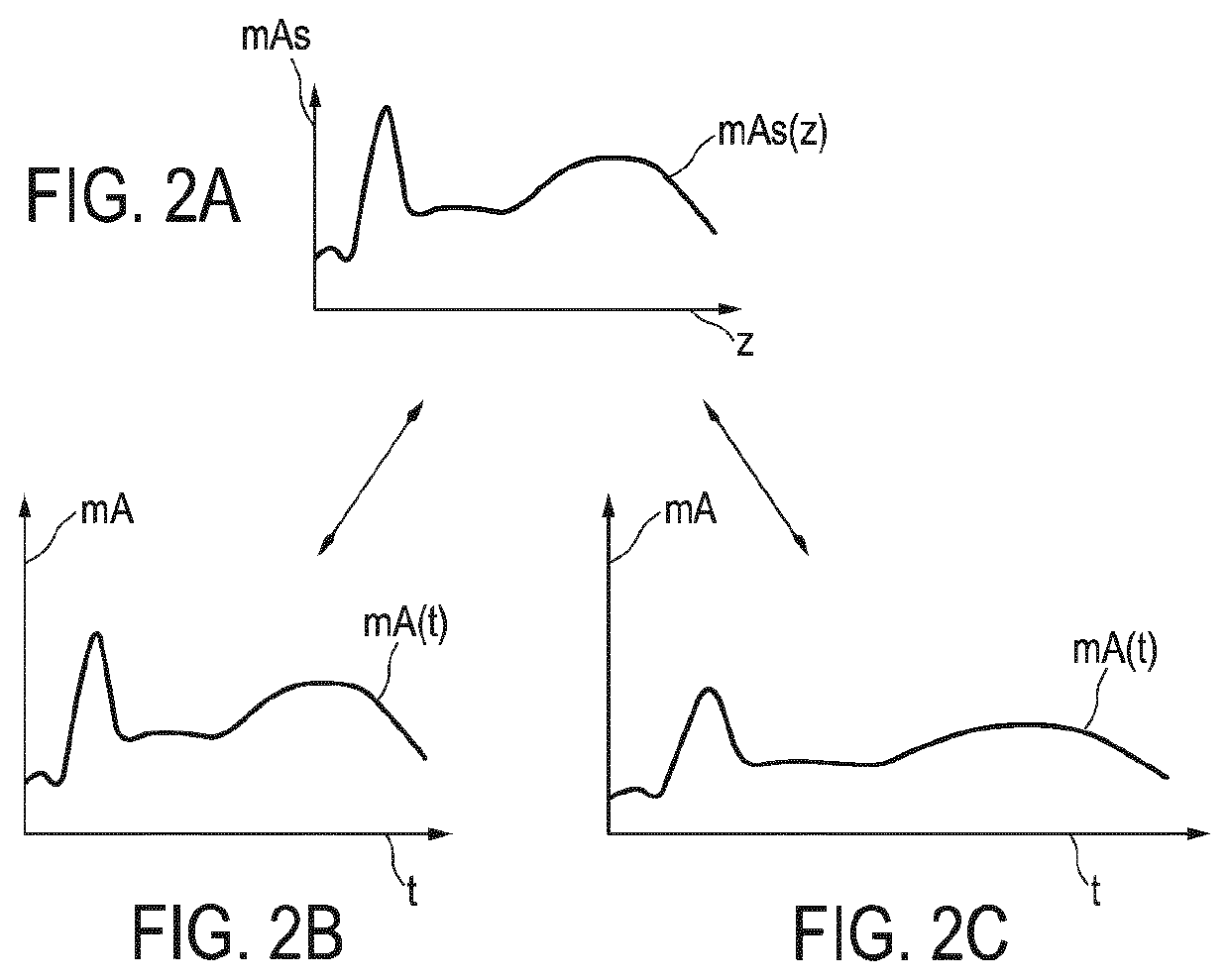
[0005]Since the exposure time determination unit of the CT device is configured for determining the object specific ET based on the max(mAs) along the z-axis and the max(mA), a reduced ET can be achieved that allows to determine values of the scan parameters that allow to achieve an image quality that allows to derive details of interest of the object from the image of the scan of the object sufficient for analyzing the object, for example for answering a clinical question. The CT device allows to achieve an appropriate pixel noise and to reduce motion artifacts, in particular motion artifacts in chest and abdomen scans of a patient and in CT angiography (CTA). Since the object specific ET is determined for the scan of the object, too long ET is avoided which reduces motion artifacts. Furthermore, since the object specific ET is determined for the scan of the object, too short ET is avoided. Too short ET may lead to clipped mAs(z) profiles which may result in generation of images with bad image quality, i.e., images with poor signal-to-noise ratio.
[0073]The method can comprise a step of iteratively adapting the values of the scan parameters until an end condition occurs. One end condition can for example be that the tube can perform the scan of the object based on the adapted values of the scan parameters. Another end condition can be that a difference of the values of the scan parameters between two subsequent iteration steps is below a threshold value. Yet another end condition can be that a user manually selects to perform the scan based on the values of the scan parameters determined in the current iteration step. Adapting the values of the scan parameters iteratively allows to find improved values of the scan parameters.

Problems solved by technology

Too short ET may lead to clipped mAs(z) profiles which may result in generation of images with bad image quality, i.e., images with poor signal-to-noise ratio.

Method used


Image

  • CT scan parameter optimization
  • CT scan parameter optimization
  • CT scan parameter optimization

Examples


first embodiment

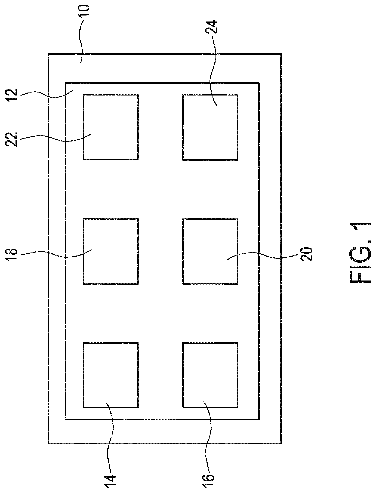
[0134]FIG. 6 shows a method for operating the CT device. The CT device operated using the method can for example be the embodiment of the CT device as presented in FIG. 1. The CT device can be integrated in a spiral CT system, for example the spiral CT system as presented in FIG. 5.

[0135]In the method an object specific ET is determined based on a max(mAs) value along a z-axis of an object and a max(mA) value of a tube used for a scan of the object. The max(mA) value depends on a tube voltage and maximal electric power of the tube at given focal spot. The mAs(z) profile is based on a dose index value or a pixel noise index value for the scan of the object, the tube voltage, and an object size(z) along the z-axis. Values of scan parameters for a scan of the object are determined based on the object specific ET. The method allows an improved determination of the values of the scan parameters for the scan of the object. The values of the scan parameters determined using the method allo...

second embodiment

[0159]FIG. 7 shows the method for operating the CT device. In this embodiment of the method the tube voltage can be iteratively adapted in order to optimize the object specific ET.

[0160]When at a given tube voltage the max(mA) value that the tube can be operated with is reached, changing the tube voltage can allow to reduce the object specific ET. In order to allow the pixel noise to be kept at least almost constant when changing the tube voltage, the CTDI is kept constant. In this embodiment, this allows to reduce the ET by up to

[0161](kVp2kVp1)1.9

with kVp2 being the adapted kilovoltage peak of the tube voltage and kVp1 being the previous kilovoltage peak of the tube voltage. Adapting the tube voltage can be used to decrease motion artifacts in scans in which an impact of a high tube voltage on contrast is less relevant and ET can be reduced.

[0162]Steps 100 to 180 and 200 to 212 correspond to the steps as presented for the embodiment of the method presented in FIG. 6 with the diffe...


PUM


Abstract

The present invention relates to optimizing values for scan parameters for a scan of an object. An object specific exposure time is determined based on a maximal required value of a z-dependent tube current by exposure time product along a z-axis of the object and a maximal available tube current value of a tube used for the scan of the object (140). The maximal available tube current value depends on a tube voltage and maximal electric power of the tube at given focal spot area (110) and the z-dependent tube current by exposure time product profile is based on a dose index value or a pixel noise index value for the scan of the object, the tube voltage, and a z-dependent object size along the z-axis (120). The object specific exposure time is used for determining values of the scan parameters for the scan of the object (150).

Description

FIELD OF THE INVENTION[0001]The present invention relates to a computed tomography (CT) device, a CT system, a method for operating the CT device, and a computer program for operating the CT device. In particular the invention relates to a CT device for scan parameter optimization.BACKGROUND OF THE INVENTION[0002]US 2014 / 0270053 A1 shows a system for optimizing CT radiation dose in the clinical setting. Mathematical models are used for estimating patient size, image noise, size-specific radiation dose, and image quality targets based on digital image data and radiologists preferences. A prediction model estimates the scanner's tube current modulation and predicts image noise and size-specific radiation dose over a range of patient sizes. An optimization model calculates specific scanner settings needed to attain target image quality at the minimum radiation dose possible. An automated system processes the image and dose data according to the mathematical models and stores and displa...

Claims


Application Information

Patent Timeline
Patent Type & Authority Patents(United States)
IPC IPC(8): A61B6/03A61B6/00A61B6/04A61B6/06
CPCA61B6/405A61B6/032A61B6/0407A61B6/06A61B6/544A61B6/4488A61B6/488A61B6/545
Inventor NAE, YAEL HAYAFELDMAN, ANDREIMISHLOVSKY, IDANNARAYANAN, SURESH
Owner KONINKLJIJKE PHILIPS NV
Why Eureka
Eureka Blog
Learn More