Device for improving performance in STED and RESOLFT microscopy using a single phase mask

a technology of phase plate and resolft, which is applied in the field of phase plate or spatial light modulator device, can solve the problems of reducing the efficiency of secondary excitation area, and significantly weakening the improvement of lateral resolution

Active Publication Date: 2022-11-01
INST DE BIOLOGIA MOLECULAR E CELULAR IBMC
View PDF8 Cites 1 Cited by
  • Summary
  • Abstract
  • Description
  • Claims
  • Application Information

AI Technical Summary

Benefits of technology

[0019]The phase masks and methods disclosed for STED and RESOLFT microscopy may advantageously be applied to provide a significant reduction in the degrees of freedom for alignment and a consequential improvement in beam quality, namely a minimized central intensity, and result in a significantly improved axial performance, increased resolution and signal level. They may equally provide an improved optical sectioning performance relative to the 2D STED mode.DESCRIPTION OF THE INVENTION
[0020]The present invention discloses a phase plate for STED and RESOLFT that results from the imprinting of a new bivortex mathematical function on a single phase mask or on a phase plate that allows some freedom in shaping the beam to a 2D / 3D hybrid regime and results in a significantly improved axial performance. Here the STED operation mode provided by the action of the bivortex phase mask or phase plate is called ‘coherent-hybrid STED’ (CH-STED).
[0021]A clear advantage of the CH-STED phase mask is a significant reduction in the degrees of freedom for alignment and the consequential improvement in beam quality, namely a minimized central intensity, with an increased signal level
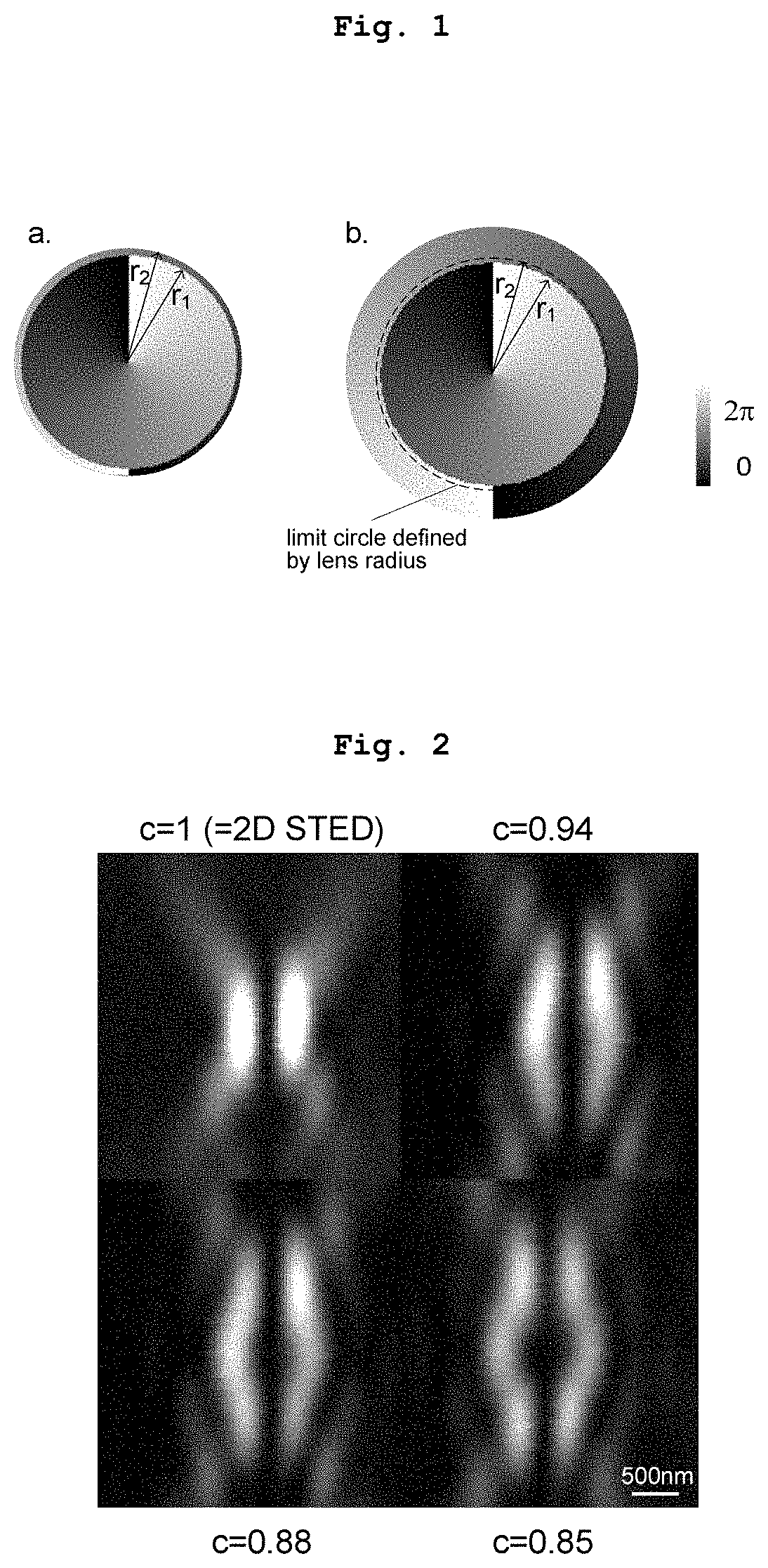
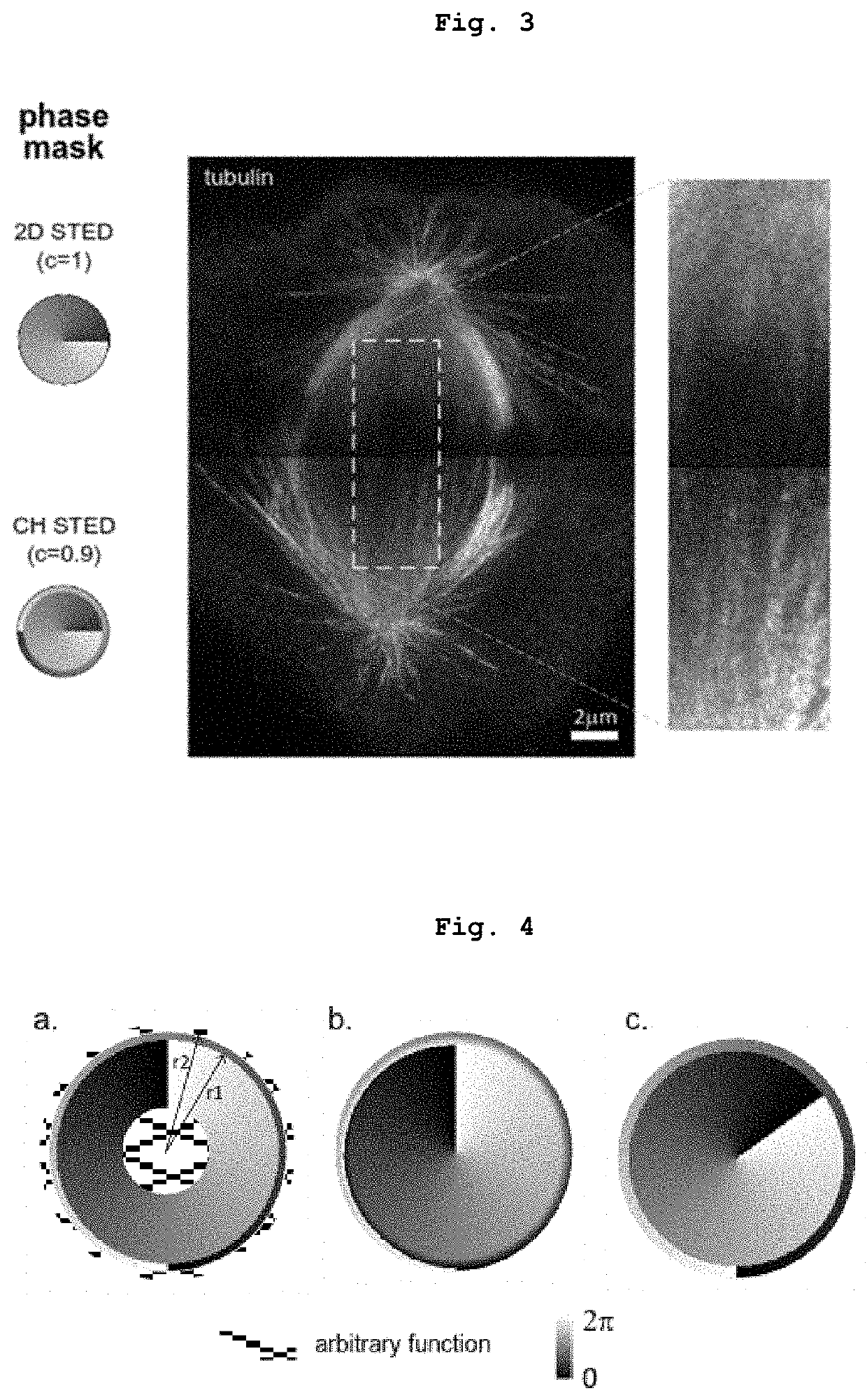
[0027]The generated bivortex phase mask (Eq. 1 and FIG. 1) provides the base structure that delivers qualitative improvement in axial performance (optical sectioning, axial resolution) over the pure 2D STED mode (FIG. 3).
[0034]Further, in another embodiment of the present invention the bivortex can be defined by a complete □ radians inter-vortex transition (a=1, as in FIGS. 4a,b) or an incomplete one (a≠1, FIG. 4c), as it does not compromise the generation of the required dark spot in the center.
[0036]The action of the CH bivortex phase mask described above is embodied in a physical phase modulating device that is placed along the path of the STED laser beam. The device that defines the phase mask can be either a structured plate (comprising structured polymer or glass, for example) or a dynamically addressable device (such as spatial light modulator). The different sections of the optical beam that passes through the device will suffers phase shifts according to the CH phase mask imprinted, thereby transforming the beam.

Problems solved by technology

Fluorescence microscopy is conventionally limited to a resolution of approximately one half of the wavelength of the radiation used to excite the fluorescent sample.
However, this 2D STED method does not improve axial resolution (typ.
However, it does so at the expense of a significantly weaker improvement in lateral resolution and a more inefficient depletion of secondary excitation areas, as compared to the 2D STED mode, making 3D STED inherently noisier than 2D STED.
Beam imperfections and relative misaligments in IH STED generate complex compound aberration effects, as well as an unwanted filling up of the central zero (Antonello et al., 2016, Booth et al., 2015), which compromises resolution improvement, decreases detectable signal and may compromise symmetry of the depletion.

Method used


Image

  • Device for improving performance in STED and RESOLFT microscopy using a single phase mask
  • Device for improving performance in STED and RESOLFT microscopy using a single phase mask

Examples


example 1

n of a Phase Plate Generating the Bivortex Phase Mask

[0045]In an example, the bivortex phase mask of the present invention is generated by a phase plate device. Such device can be produced by crafting the negative of the bivortex phase mask of the present invention's phase plate onto a mold and by developing the mold to obtain a bivortex phase plate. The manufacture by molding may be achieved by methods known in the art, for example those described by Oemrawsingh et al, 2004, with the addition of comprising a step of: designing the mold as a negative of the present invention's phase mask. After release of the mold, a solid phase plate with a bivortex configuration is obtained.

example 2

n of the Bivortex Phase Mask by a Spatial Light Modulator

[0046]In another example, the bivortex phase mask of the present invention can be generated by a spatial light modulator device (SLM). Such SLM can be produced by integrating complementary metal-oxide-semiconductor (CMOS) in the SLM, by methods such as the ones described in the art (ZHU, et al 2004.), with the addition of comprising a step of: imprinting the present invention's bivortex phase mask onto the SLM, through electronic control of its subunits.

example 3

oscopy Method Employing a Bivortex Phase Mask Through Compensation or Correction Functions

[0047]Another example of an embodiment of the present invention refers to a method for STED microscopy that can be developed through comprising a step of: modulating the physical phase of a radiation beam on an existing phase plate or a spatial light modulator using compensation or corrective phase functions to ultimately generate the present invention's byvortex phase mask as the effective phase mask.


PUM

PropertyMeasurementUnit
radiusaaaaaaaaaa
phaseaaaaaaaaaa
RESOLFT microscopyaaaaaaaaaa

Abstract

The present invention refers to a method for high spatial resolution imaging comprising a phase plate or a spatial light modulator (SLM) device for STimulated Emission Depletion (STED) microscopy and Reversible Saturable OpticaL Fluorescence Transitions (RESOLFT) microscopy, where a bivortex pattern is imprinted on the said phase plate or SLM to generate a beam. The bivortex pattern allows some freedom in shaping the STED beam to improve the microscope's axial performance and optical sectioning capacity.The present invention further refers to a method for STED and RESOLFT microscopy comprising the step of modulating the optical phase of a laser using a phase plate or a spatial light modulator device with a phase mask comprising a bivortex with a tunable radius.The disclosed phase masks and methods of STED and RESOLFT microscopy may advantageously be applied to provide a hybrid 2D / 3D STED regime but one with a significant reduction in the degrees of freedom for alignment relative to what is found in incoherent beam superpositions, thus providing an improvement in beam quality, namely a minimized central intensity and lower sensitivity to aberrations, resulting in an increased signal level and axial performance.

Description

TECHNICAL FIELD OF THE INVENTION[0001]The present invention refers to a phase plate or a spatial light modulator device for STimulated Emission Depletion (STED) and Reversible Saturable OpticaL Fluorescence Transitions (RESOLFT) microscopy, which results from the imprinting of a bivortex mathematical function on a single phase mask that allows shaping the STED beam to deliver an improved axial performance, increased resolution and signal level.[0002]Thus, the present invention falls within the technical field of Physics, Instruments, Optics and Devices or Arrangements for the control of the phase of light.STATE OF THE ART[0003]Fluorescence microscopy is conventionally limited to a resolution of approximately one half of the wavelength of the radiation used to excite the fluorescent sample. This is known as the ‘diffraction limit’. Some techniques have been developed which circumvent this limit by harnessing the non-linear response of the fluorophores to light, such as in the family ...

Claims


Application Information

Patent Timeline
Patent Type & Authority Patents(United States)
IPC IPC(8): G02B21/00G02B21/36G02B27/58
CPCG02B21/361G02B21/0032G02B27/58G02B21/0076G02B21/0056G01N21/6458
Inventor ABRANTES GUEDES DA FONSECA PEREIRA, ANTÓNIO JOSÉ
Owner INST DE BIOLOGIA MOLECULAR E CELULAR IBMC
Why Eureka
Try Eureka