Tilt detection apparatus and method thereof

a technology of tilt detection and apparatus, applied in the field of measuring arrangements, to achieve the effect of reducing costs, simplifying the assembly of the apparatus, and reducing the cost of the apparatus

Active Publication Date: 2022-11-08
ABB (SCHWEIZ) AG
View PDF36 Cites 0 Cited by
  • Summary
  • Abstract
  • Description
  • Claims
  • Application Information

AI Technical Summary

Benefits of technology

[0008]By using the apparatus or method according to present invention, no optical means, such as lens, is used for converging the light beams projected by the visible element. It is thus possible to facilitate the assembly of the apparatus, miniaturize the apparatus and reduce costs thereof. Preferably, the visible element is a portion of the image capture device facing the part having a plane reflective surface. By reuse of a portion of the image capture device as the visible element, it thereby makes the apparatus more compact and reduce costs thereof.
[0009]Preferably, a lens of the image capture device and the visible element are disposed at substantially same distance from the part having a plane reflective surface where the fixture assumes the levelling orientation. In a situation where the distances are of large difference, such configuration is helpful for increasing the accuracy of the derivation between the first virtual image and the second virtual image and thus leads to better measurement results.
[0010]Preferably, a focal length of the image capture device is maintained twice as long as its distance to the part having a plane reflective surface assuming the levelling orientation. In such arrangement, the image capture device can obtain a relatively clear image of the pattern in the mirror without adjustment of the focus too much.

Problems solved by technology

A small levelling error of the fixture can cause final alignment error.
For example, in assembling a 100 mm*100 mm sheet, levelling error at 1° causes 0.025 mm alignment error.
As a characteristics of detection is influenced by positions and the like of the configured photodetector, the light source and the lens, positioning thereof requires relatively high accuracy and manufacturing involves considerable difficulties.
Furthermore, since the light beams emitted from the light source are converged by the lens before they reach the reflector, the incident area of the reflector becomes relatively narrow.
Under a worse situation where the reflector would be disposed outside of the incident area as defined by the lens, the autocollimator will not work.

Method used


Image

  • Tilt detection apparatus and method thereof
  • Tilt detection apparatus and method thereof
  • Tilt detection apparatus and method thereof

Examples


Embodiment Construction

[0023]In the following description, for purposes of explanation and not limitation, specific details are set forth, such as particular circuits, circuit components, interfaces, techniques, etc. in order to provide a thorough understanding of the present invention. However, it will be apparent to one skilled in the art that the present invention may be practiced in other embodiments that depart from these specific details. In other instances, detailed descriptions of well-known methods and programming procedures, devices, and circuits are omitted so not to obscure the description of the present invention with unnecessary detail.

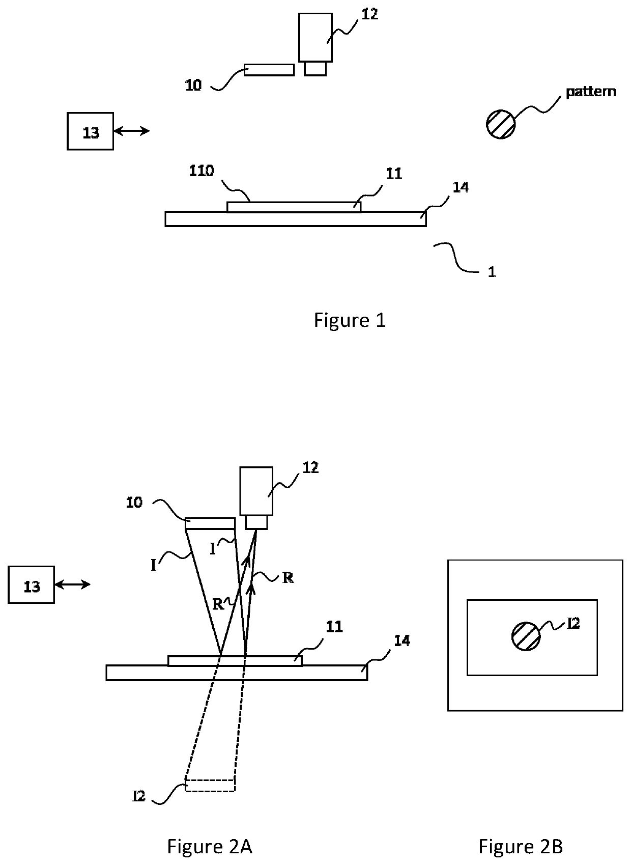
[0024]FIG. 1 shows an apparatus for detecting tilt of a fixture according to a first embodiment of present invention. As shown in FIG. 1, the apparatus 1 includes a visible element 10, a part having a plane reflective surface 11, an image capture device 12 and a controller 13.

[0025]The visible element 10 has a pattern visibly distinguishable from its surroundi...


PUM


Abstract

An apparatus for detecting tilt of a fixture and method thereof. The apparatus includes a visible element having a pattern visibly distinguishable from its surrounding area; a part having a plane reflective surface being configured to be engaged with the fixture in alignment and being arranged to reflect light beams propagating directly from the visible element so as to produce a first virtual image of the visible element; an image capture device being disposed at same side of the visible element with respective to the part having a plane reflective surface and being configured to have a field of view covering the first virtual image and a second virtual image of the visible element produced by the part having a plane reflective surface, wherein the second virtual image was produced where the part having a plane reflective surface assumed a levelling orientation; and a controller being adapted for detecting tilt of the fixture using a deviation of the first virtual image from the second virtual image of the visible element in the field of view of the image capture device. By using the apparatus or method according to present invention, no optical means, such as lens, is used for converging the light beams projected by the visible element. It is thus possible to facilitate the assembly of the apparatus, miniaturize the apparatus and reduce costs thereof.

Description

TECHNICAL FIELD[0001]The invention relates to measuring arrangements by use of optical means, and more particularly to detecting tilt angle of a fixture by use of optical means.BACKGROUND ART[0002]In electronics production, it requires a relatively high geometry alignment accuracy for assembling small parts, such as sheet or ring-shaped ones. Robot assembly system has several advantages in handling small part assembly, for example higher production output rate, lower operating cost, better process quality, safer workplace and so on. A fixture is normally provided for holding the parts so that they can be disposed in desirable place and orientation.[0003]A small levelling error of the fixture can cause final alignment error. For example, in assembling a 100 mm*100 mm sheet, levelling error at 1° causes 0.025 mm alignment error. Therefore, levelling measurement of the fixture is required in accurate assembly.[0004]Autocollimator is an optical instrument for non-contact measurement of ...

Claims


Application Information

Patent Timeline
Patent Type & Authority Patents(United States)
IPC IPC(8): G01C9/06G01B11/26G01D5/30
CPCG01C9/06G01B11/26G01D5/30G01C2009/066
Inventor GU, HAOTIAN, JIHUANLI, CHENGKEFER, MARTIN
Owner ABB (SCHWEIZ) AG
Why Eureka
Try Eureka