Piezoelectric component, sensor, and actuator

a technology of piezoelectric elements and actuators, applied in the direction of piezoelectric/electrostrictive/magnetostrictive devices, electrical apparatus, acceleration measurement using interia forces, etc., can solve the problems of difficult composition control, cracks may easily be generated at the part when the piezoelectric element deflects, and the piezoelectric element described in patent document 1 may crack

Active Publication Date: 2022-11-22
MURATA MFG CO LTD
View PDF26 Cites 0 Cited by
  • Summary
  • Abstract
  • Description
  • Claims
  • Application Information

AI Technical Summary

Benefits of technology

[0024]According to the present invention, it is possible to provide a piezoelectric component including a piezoelectric element enabling breakage of the piezoelectric element to be suppressed even in a case in which the piezoelectric element includes no substrate, and in which the piezoelectric element is thin (100 μm or less), a sensor including the piezoelectric component, and an actuator including the piezoelectric component.

Problems solved by technology

However, even the piezoelectric element described in Patent Document 1 may crack when the piezoelectric element significantly deflects in a case in which the piezoelectric element is thin (100 μm or less).
Also, in Patent Document 2, since the insulating film has a partially opened part for electrode extension, cracks may easily be generated at the part when the piezoelectric element deflects.
Patent Document 3 also has a problem in which, since the material is formed by a hydrothermal synthesis method, it is difficult to control the compositions, desired characteristics cannot be obtained, and characteristics variation is significant.

Method used


Image

  • Piezoelectric component, sensor, and actuator
  • Piezoelectric component, sensor, and actuator
  • Piezoelectric component, sensor, and actuator

Examples


embodiment 1

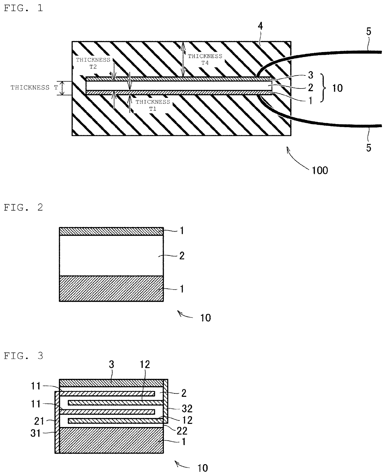
[0037]Referring to FIGS. 1 to 4, a piezoelectric component 100 according to the present invention includes a piezoelectric element 10 including a piezoelectric ceramic layer 2 and a sintered metal layer 1 provided on at least one main surface of the piezoelectric ceramic layer 2 and containing a non-precious metal. The piezoelectric element 10 may also include an external electrode layer 3 on an opposite surface of the piezoelectric ceramic layer 2 to the surface provided with the sintered metal layer 1.

Protective Layer

[0038]Both the main surfaces of the piezoelectric element 10 are entirely covered with a protective layer 4 containing an elastic body. Both the main surfaces of the piezoelectric element 10 are entirely (preferably uniformly) covered with the protective layer 4 in order for the piezoelectric ceramic layer 2 and the sintered metal layer 1 not to be exposed, to cause any stress applied to the piezoelectric element 10 to be distributed, and to prevent breakage of the pi...

embodiment 2

[0083]A piezoelectric component according to the present embodiment differs from that according to Embodiment 1 in that the piezoelectric element 10 in the piezoelectric component 100 illustrated in FIG. 1 is changed to a piezoelectric element 10 illustrated in FIG. 3. The present embodiment is similar to Embodiment 1 in the other respects.

[0084]The piezoelectric element 10 used in Embodiment 2 includes a piezoelectric ceramic layer 2 formed integrally with a sintered metal layer 1 and formed, for example, in a substantially rectangular parallelepiped shape. The piezoelectric ceramic layer 2 includes therein two first internal electrodes 11 and two second internal electrodes 12 and includes a first connection electrode 31 and a second connection electrode 32 on a first side surface 21 and a second side surface 22 of the piezoelectric ceramic layer 2 opposed to each other, respectively. Meanwhile, although each number of the first internal electrodes 11 and the second internal electr...

embodiment 3

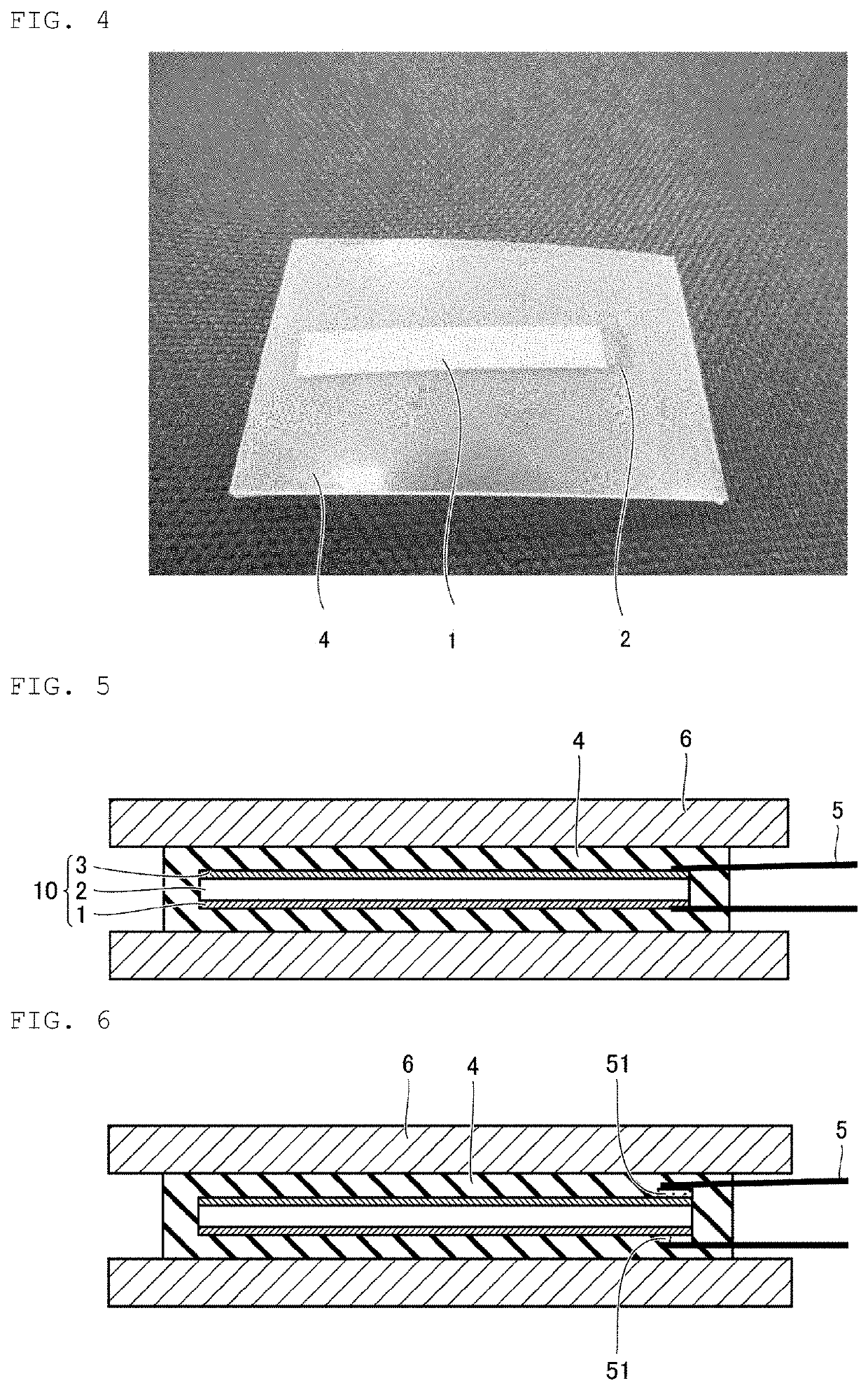
[0087]As illustrated in FIG. 5, the piezoelectric component 100 described above in Embodiments 1 and 2 may further include a reinforcing member 6 on an opposite main surface of the protective layer 4 to a surface in contact with the piezoelectric element 10. The reinforcing member 6 may cover, for example, the opposite main surface of the protective layer 4 to the surface in contact with the piezoelectric element 10, that is, the entire main surface not in contact with the piezoelectric element 10, and may further cover the end surface of the protective layer 4 or the piezoelectric element 10. The reinforcing member 6 may cover one surface out of the opposite main surfaces of the protective layer 4 to the surfaces in contact with the piezoelectric element 10 or may cover both the upper and lower surfaces. The entire main surface of the protective layer 4 is preferably uniformly covered with the reinforcing member 6. In a case in which the reinforcing members 6 are provided on both t...


PUM

PropertyMeasurementUnit
thicknessaaaaaaaaaa
Young's modulusaaaaaaaaaa
thicknessaaaaaaaaaa

Abstract

A piezoelectric component that has a piezoelectric element including a piezoelectric ceramic layer and a sintered metal layer on at least a first main surface of the piezoelectric ceramic layer and containing a non-precious metal, and a protective layer containing an elastic body covering first and second opposed main surfaces of the piezoelectric element. The piezoelectric ceramic layer contains 90 mol % or more of a perovskite compound that contains niobium, an alkali metal, and oxygen. A thickness of the piezoelectric element is 100 μm or less.

Description

CROSS REFERENCE TO RELATED APPLICATIONS[0001]The present application is a continuation of International application No. PCT / JP2018 / 038809, filed Oct. 18, 2018, which claims priority to Japanese Patent Application No. 2017-216623, filed Nov. 9, 2017, the entire contents of each of which are incorporated herein by reference.FIELD OF THE INVENTION[0002]The present invention relates to a piezoelectric component, a sensor, and an actuator.BACKGROUND OF THE INVENTION[0003]A piezoelectric device mainly including a piezoelectric ceramic is widely used as an actuator and each of various sensors. For example, in a piezoelectric actuator, input electric energy is converted into mechanical energy by an inverse piezoelectric effect, and the piezoelectric actuator controls driving of various electronic devices. Also, in a piezoelectric sensor, input mechanical energy is converted into electric energy by a piezoelectric effect, and the piezoelectric sensor can measure a pressure value, acceleratio...

Claims


Application Information

Patent Timeline
Patent Type & Authority Patents(United States)
IPC IPC(8): G01P15/08H01L21/00H01L41/187H01L41/047H01L41/083H01L41/09H01L41/113H01L41/273
CPCH01L41/1873H01L41/0477H01L41/083H01L41/09H01L41/113H01L41/273H10N30/877H10N30/883H10N30/875H10N30/8542H10N30/20H10N30/30H10N30/50H10N30/053
Inventor OGAWA, HIROZUMI
Owner MURATA MFG CO LTD
Why Eureka
Try Eureka