Vibrator, manufacturing method of vibrator, electronic apparatus, and moving object
a manufacturing method and vibrator technology, applied in the direction of generators/motors, microstructure devices, coatings, etc., can solve the problem of mems vibrator breakage risk, and achieve the effect of suppressing the breakage of the mems vibrator 100
- Summary
- Abstract
- Description
- Claims
- Application Information
AI Technical Summary
Benefits of technology
Problems solved by technology
Method used
Image
Examples
embodiment
[0049]A vibrator according to the embodiment will be described with reference to FIGS. 1 to 9G2.
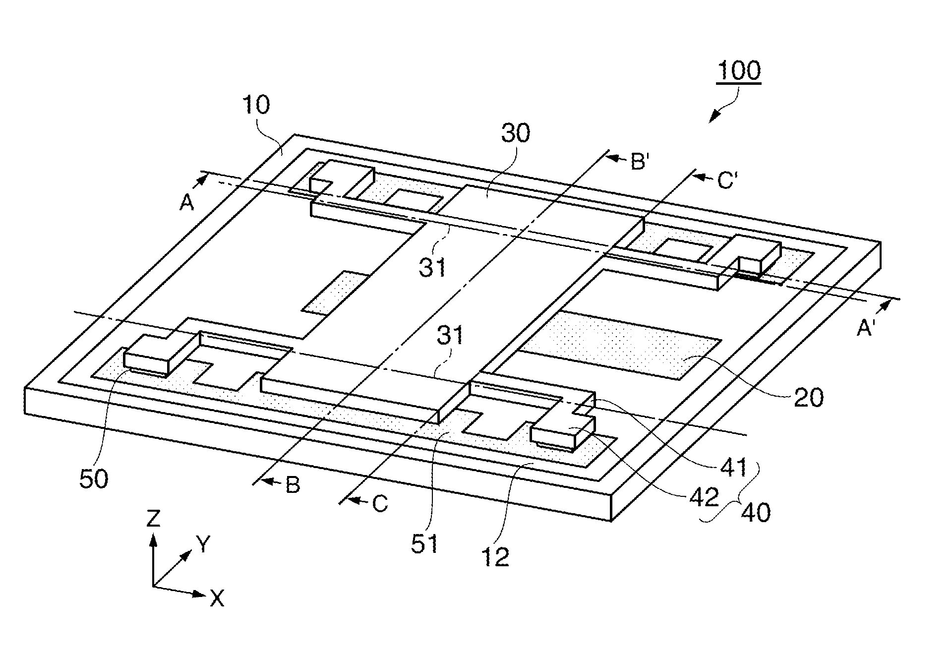
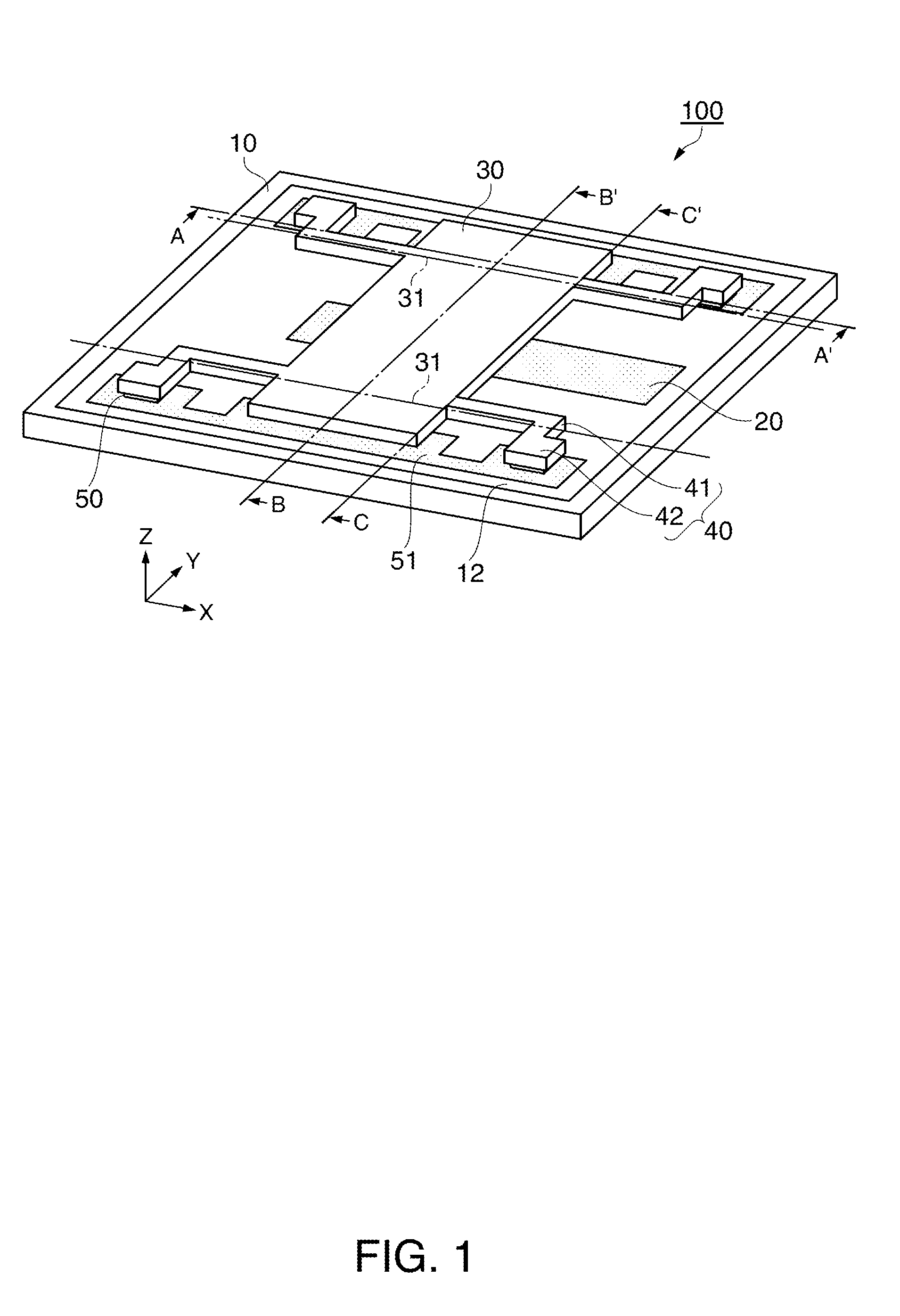
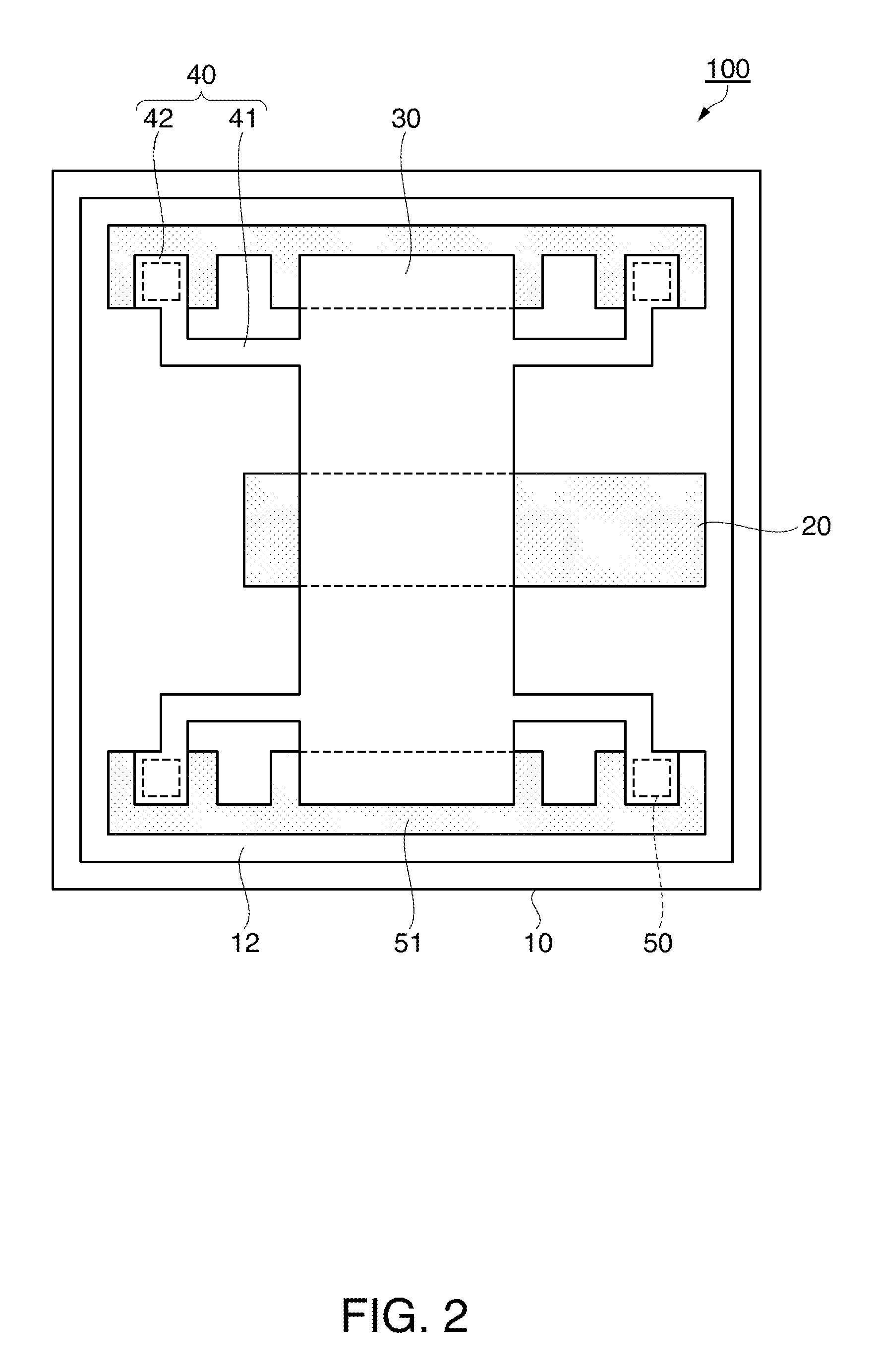
[0050]FIG. 1 is a perspective view schematically showing a MEMS vibrator as the vibrator according to the embodiment. FIG. 2 is a plan view schematically showing the MEMS vibrator. FIGS. 3 and 4 are cross-sectional views schematically showing cross-sections of the MEMS vibrator shown in FIG. 1. FIG. 5 is an enlarged view schematically showing, in an enlarged manner, a portion of a support portion of the MEMS vibrator shown in FIG. 1. FIGS. 6A1 to FIG. 9G2 are step diagrams for explaining a manufacturing method of the MEMS vibrator as the vibrator according to the embodiment.
[0051]The MEMS vibrator 100 as the vibrator according to the embodiment includes, above a substrate 10, a vibrating portion 30, support portions 40 extended from the vibrating portion 30, and fixing portions 50 fixing the support portions 40. Moreover, the MEMS vibrator 100 includes, on the substrate 10 as a base porti...
modified example 1
[0112]FIG. 10A is an enlarged perspective view of a support portion 140 of a MEMS vibrator 101 according to Modified Example 1.
[0113]The MEMS vibrator 101 is a MEMS vibrator including a free-free beam movable electrode similarly to the MEMS vibrator 100. The MEMS vibrator 101 is configured to include the substrate 10, the lower electrode 20, the vibrating portion 30, the fixing portion 50, and the support portion 140. In FIG. 10A, the illustration of these components is partially omitted.
[0114]The support portion 140 differs from the support portion 40 of the MEMS vibrator 100 described above in the shape of a beam portion 141. The beam portion 141 includes a beam portion 141a, a beam portion 141b, and a beam portion 141c between the vibrating portion 30 and the fixing portion 50, where the beam portion 141 is extended therebetween.
[0115]In the support portion 140, the beam portion 141a as a first beam portion is extended in the first direction (X-axis direction) from the vibrating ...
modified example 2
[0124]FIG. 10B is an enlarged perspective view of a support portion 240 of a MEMS vibrator 102 according to Modified Example 2.
[0125]The MEMS vibrator 102 is a MEMS vibrator including a free-free beam movable electrode similarly to the MEMS vibrator 100. The MEMS vibrator 102 is configured to include the substrate 10, the lower electrode 20, the vibrating portion 30, the fixing portion 50, and the support portion 240. In FIG. 10B, the illustration of these components is partially omitted.
[0126]The support portion 240 differs from the support portion 40 of the MEMS vibrator 100 described above in the shape of a beam portion 241.
[0127]The beam portion 241 includes a beam portion 241a, a beam portion 241b, a beam portion 241c, a beam portion 241d, and a beam portion 241e between the vibrating portion 30 and the fixing portion 50, where the beam portion 241 is extended therebetween.
[0128]In the support portion 240, the beam portion 241a as a first beam portion is extended in the first d...
PUM
| Property | Measurement | Unit |
|---|---|---|
| angle | aaaaa | aaaaa |
| thickness | aaaaa | aaaaa |
| length | aaaaa | aaaaa |
Abstract
Description
Claims
Application Information
 - R&D
- Intellectual Property
- Life Sciences
- Materials
- Tech Scout
- Unparalleled Data Quality
- Higher Quality Content
- 60% Fewer Hallucinations
Browse by: Latest US Patents, China's latest patents, Technical Efficacy Thesaurus, Application Domain, Technology Topic, Popular Technical Reports.
© 2025 PatSnap. All rights reserved.Legal|Privacy policy|Modern Slavery Act Transparency Statement|Sitemap|About US| Contact US: help@patsnap.com


