
Computer on a card with a remote human interface

a human interface and computer technology, applied in the field of computer systems, can solve the problems of increasing complexity and cost of managing such resources, unauthorized software installation, data protection and software control,

Inactive Publication Date: 2001-04-26
CLEARCUBE TECHNOLOGY INC
View PDF98 Cites 22 Cited by
  • Summary
  • Abstract
  • Description
  • Claims
  • Application Information

AI Technical Summary

Benefits of technology

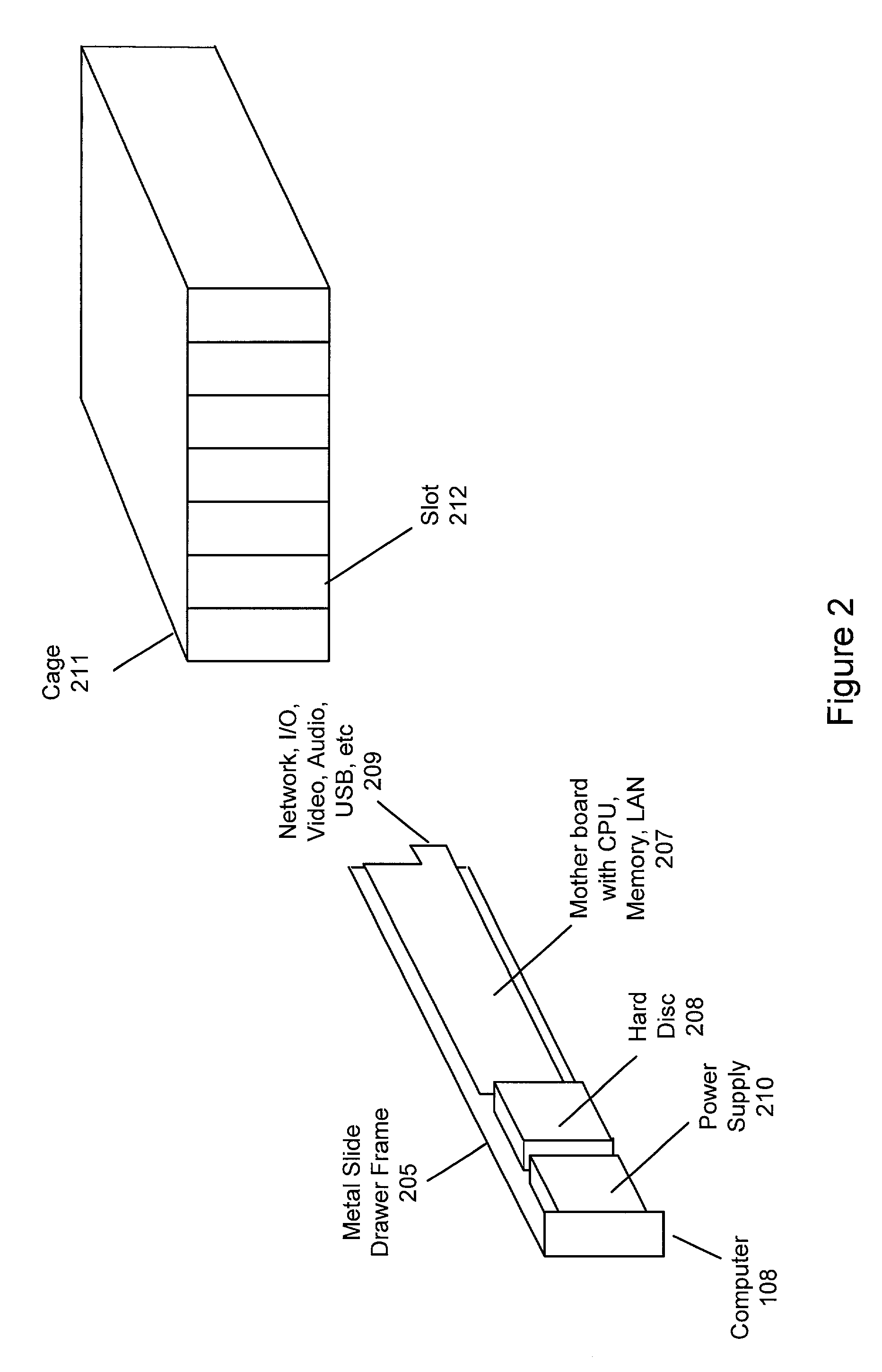
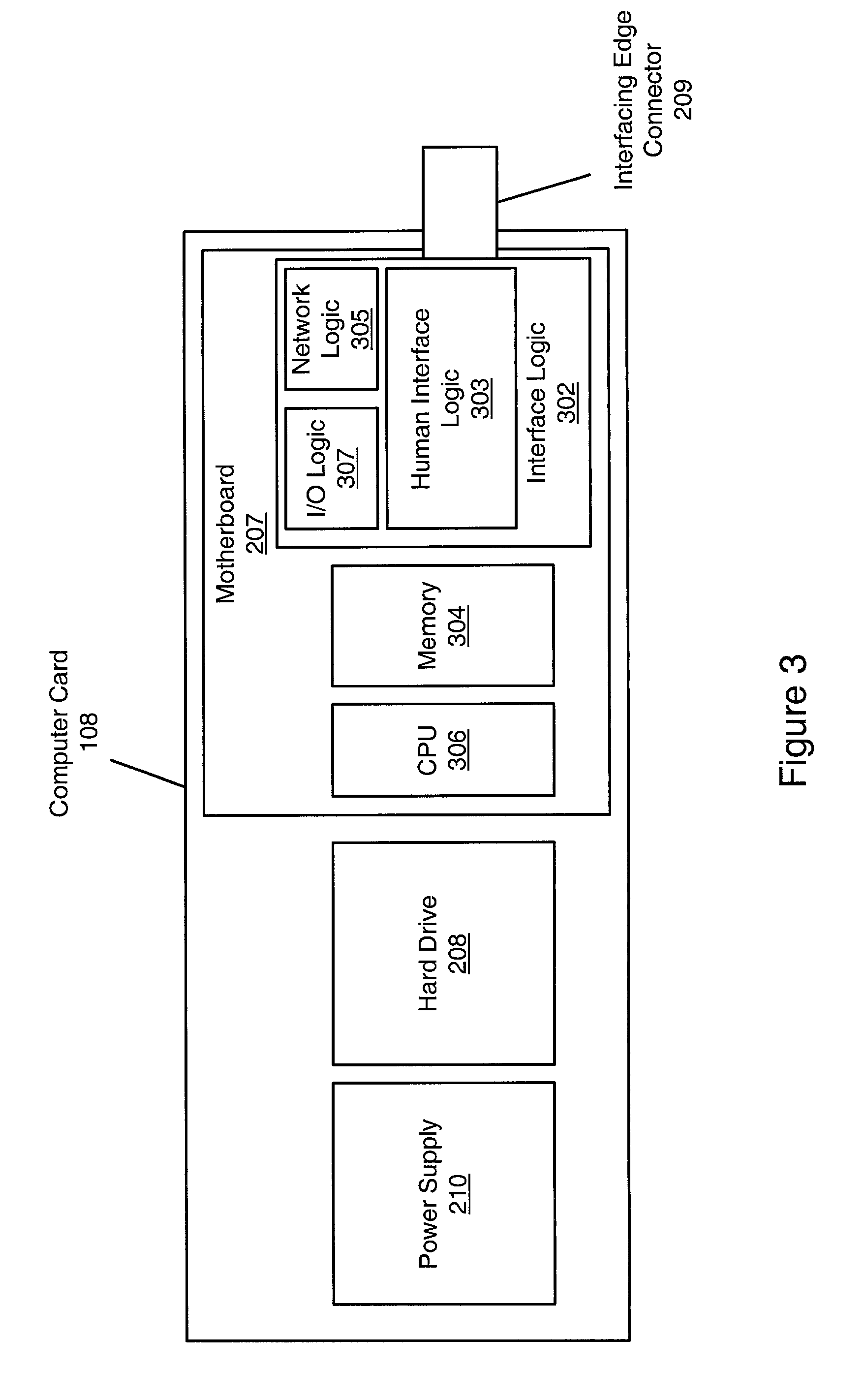
19. Each computer card may also be coupled to one or more networks through the onboard network logic. The networks may be one or more of a Local Area Network (LAN) or a Wide Area Network (WAN), such as the Internet. In one embodiment, the computer cards may be inserted into respective slots of the cage, and coupled to respective user interfaces through the cage connector and one or more human interface cables. In one embodiment, each computer card may also be coupled to the one or more networks through the cage connector and one or more network cables, such as an Ethernet cable.
20. In one embodiment, the motherboard ...

Problems solved by technology

As the number of networked computer systems utilized in an enterprise increases, the management of such resources becomes increasingly complex and expensive.
Some of the manageability issues involved in maintaining a large number of networked computer systems include ease of installation and deployment, the topology and physical logistics of the network, asset management, scalability (the cost and effort involved in increasing the number of units), troubleshooting network or unit problems, support costs, software tracking and management, as well as the simple issue of physical space, be it floor space or room on the desktop.
In addition, there are security issues regarding physical assets, data protection, and software control, as well as computer virus issues.
Ensuring that unauthorized software is not installed on any of the machines in the network involves periodically personally auditing the software contents of each machine, at substantial cost in time and effort.
However, there are numerous disadvantages with these approaches due to the fact that various compromises in size and feature set have been made to accommodate a wide assortment of feature addition cards.
Such disadvantages include a higher product cost and a large physical size for each unit.
In addition, the terminations and connections at the back of each unit are awkward to use--in the case of the first approach the terminations are on the motherboard, requiring the removal of all connectors before removing the board from its slide drawer case; in the case of the back plane based system the edge connections for each card have a high number of connections which creates a connection environment which is both fragile and difficult to administer.
Finally, the power supply for the computers is typically part of the drawer holding cabinet and is not located on the slide drawer, which means that there is a single point of failure for the entire system, i.e., if the power supply fails, all the computers fail.
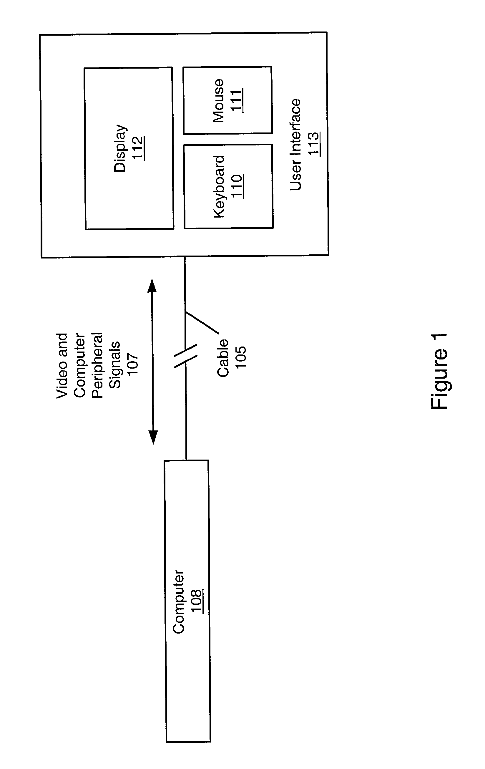
8. If the computer systems are not used as servers, there is the additional issue of coupling each PC's human interface (HI) components to the computers in the central cabinet.
Locating each unit's HI at a remote location may be problematic due to distance limitations, such as those associated with the Universal Serial Bus (USB) protocol, and complex cabling requirements for transmission of video and computer peripheral signals.
Current prior art systems which utilize commonly located computing systems have not provided any mechanism or logic on the computing system which enables the human interface associated with the computing system to be located at a remote location.

Method used


Image

  • Computer on a card with a remote human interface
  • Computer on a card with a remote human interface
  • Computer on a card with a remote human interface

Examples


Embodiment Construction

Incorporation by Reference

28. U.S. Provisional Patent No. 60 / 144,809 titled "A Technique To Extend The Operating Distance Of A Universal Serial Bus" is hereby incorporated by reference in its entirety as though fully and completely set forth herein.

29. U.S. Pat. No. 6,119,146 titled "Computer Network Having Multiple Remotely Located Human Interfaces Sharing A Common Computing System", which was filed May 4, 1998, whose inventors are Barry Thornton, Andrew Heller, Daniel Barrett, and Charles Ely, is hereby incorporated by reference in its entirety as though fully and completely set forth herein.

30. U.S. Pat. No. 6,038,616 titled "Computer System With Remotely Located Interface Where Signals Are Encoded At The Computer System, Transferred Through A 4-Wire Cable, And Decoded At The Interface", which was filed May 4, 1998, whose inventors are Barry Thornton, Andrew Heller, Daniel Barrett, and Charles Ely, is hereby incorporated by reference in its entirety as though fully and completely...


PUM


Abstract

A computing system in which a human interface (HI) is located remotely from a computer. The HI includes a keyboard, mouse, and monitor. The computer includes a motherboard with CPU, memory, network and interface logic, disk drives, and a power supply, configured on a single card, and communicates with the HI by sending and receiving encoded HI signals. The computer card includes an interfacing edge connector for communicating with the HI and networks. The HI logic receives HI signals from the interface logic and encodes the signals into a format suitable for transmission to the HI. The HI logic receives and decodes incoming encoded HI signals from the HI, and transmits the decoded HI signals to the interface logic for use in the computing system. The network logic encodes network signals into a format suitable for transmission to the network, and receives and decodes encoded network signals from the network.

Description

CONTINUATION DATA1. This is a continuation-in-part of U.S. patent application Ser. No. 09 / 524,812, titled COMPUTER SYSTEM HAVING REMOTELY LOCATED I / O DEVICES, which was filed Mar. 14, 2000, whose inventors are Barry Thornton, Andrew Heller, Daniel Barrett, and Charles Ely, which is a continuation of U.S. patent application Ser. No. 09 / 072,320, titled COMPUTER SYSTEM WITH REMOTELY LOCATED INTERFACE WHERE SIGNALS ARE ENCODED AT THE COMPUTER SYSTEM, TRANSFERRED THROUGH A 4-WIRE CABLE, AND DECODED AT THE INTERFACE, which was filed May 4, 1998, whose inventors are Barry Thornton, Andrew Heller, Daniel Barrett, and Charles Ely, and which issued as U.S. Pat. No. 6,038,616, which claims benefit of U.S. Provisional Application No. 60 / 069,464, filed on Dec. 15, 1997.BACKGROUND OF THE INVENTION2. 1. Field of the Invention3. The present invention relates generally to computer systems and specifically to a computer on a card with a remote human interface.4. 2. Description of the Related Art5. Ma...

Claims


Application Information

Patent Timeline
IPC IPC(8): G06F3/023G06F3/038G09G5/00
CPCG06F3/023G06F3/0231G06F3/038G09G5/006
Inventor HELLER, ANDREWTHORNTON, BARRY
Owner CLEARCUBE TECHNOLOGY INC
Learn More