
CDMA transmission power control in variable control cycle

a variable control cycle and transmission power technology, applied in power management, multiplex communication, wireless communication, etc., can solve problems such as unfavorable subscribers (or users of mobile stations), interference of desired signals, and fading of mobile communication systems

Inactive Publication Date: 2001-06-07
NEC CORP
View PDF0 Cites 17 Cited by
  • Summary
  • Abstract
  • Description
  • Claims
  • Application Information

AI Technical Summary

Benefits of technology

[0012] It is another object of this invention to provide a CDMA transmission power control method for controlling transmission power of a mobile station without practical influence of fading.
[0015] It is yet another object of this invention to provide a transmission power control system capable of deal with rapid fading without shortening a transmission power control period.

Problems solved by technology

In other words, to the desired signal, the undesired signal is interference.
This situation is undesirable for subscribers (or users of the mobile stations)
In the meantime, a mobile communication system has a problem of fading caused by the movement of the mobile stations.
Thus, the fading remarkably deteriorates a communication quality of the mobile communication system.
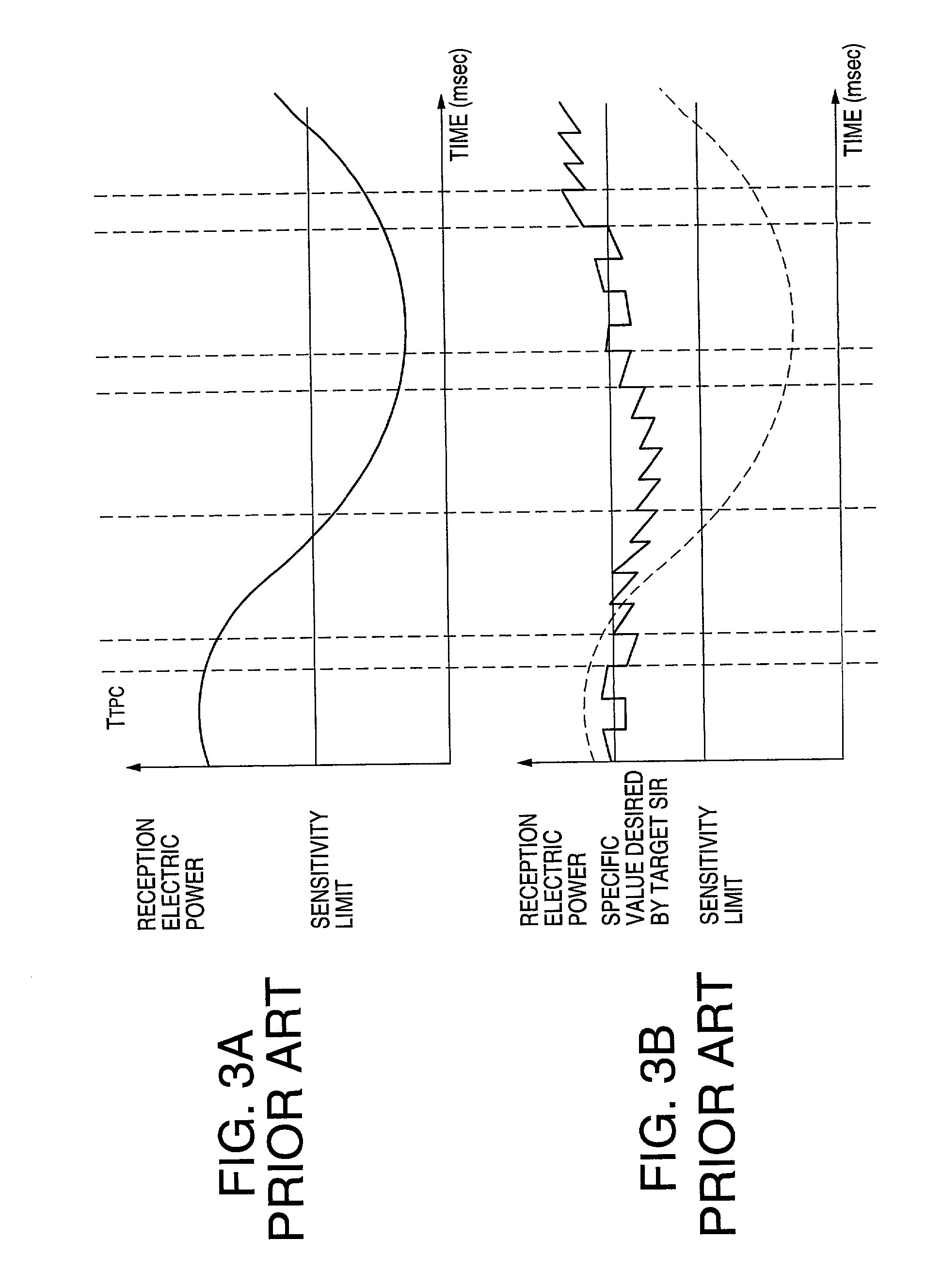
However, the conventional CDMA mobile communication system has a problem that the closed loop control cannot deal with rapid change of the fading deteriorates the receiving characteristic of the base station.
However, there is a limit to shortening of the transmission power control period T.sub.TPC because each signal processing process (e.g. modulation, estimation of the SIR and so on) needs a certain time.
In addition, the shortening of the transmission power control period T.sub.TPC requires big change of algorithm of a program for the closed power control.

Method used


Image

  • CDMA transmission power control in variable control cycle
  • CDMA transmission power control in variable control cycle
  • CDMA transmission power control in variable control cycle

Examples


Embodiment Construction

:

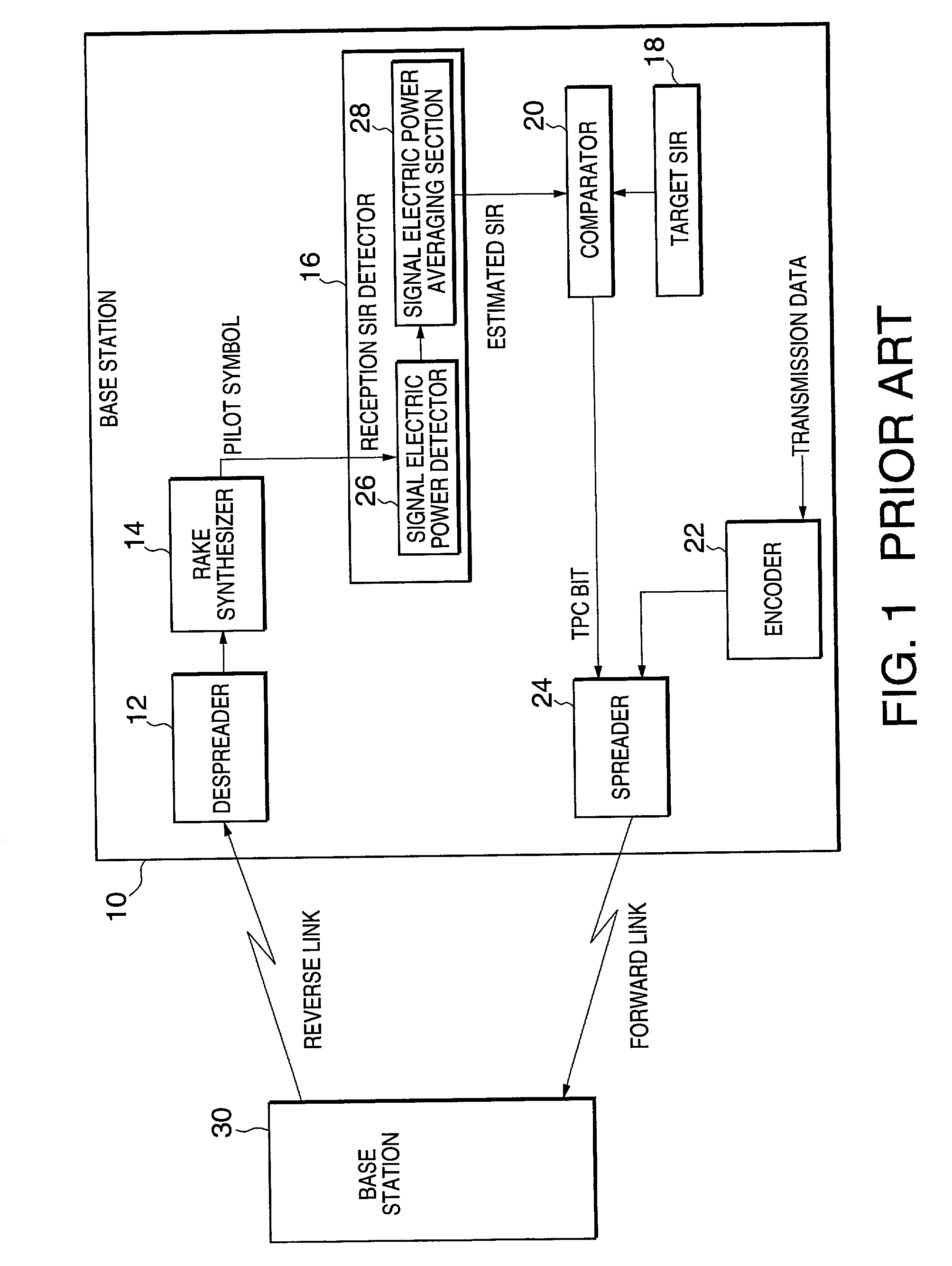
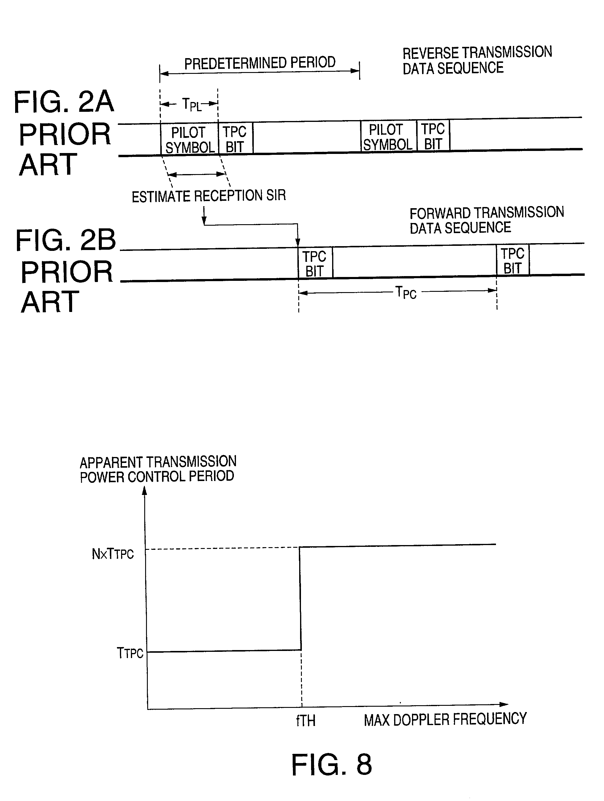
[0040] Referring to FIGS. 1 through 3, description will be at first directed to a conventional CDMA mobile communication system or a conventional CDMA transmission power control system for a better understanding of this invention.

[0041] In FIG. 1, the CDMA mobile communication system comprises a base station 10 and a mobile station 30. The base station 10 carries out a close loop control of reverse transmission power for the mobile station 30. The base station 10 includes a despreader 12, a RAKE synthesizer 14, a received SIR detector 16, a target SIR memory 18, a comparator 20, a encoder 22, and a spreader 24.

[0042] The despreader 12 is connected to a transmitting / receiving section (not show) including an antenna and supplies a received signal from the transmitting / receiving section. The received signal includes a desired multi-path signal which includes an original reverse transmission signal transmitted from the mobile station 30 through an reverse link and a plurality of deriva...


PUM


Abstract

In a CDMA transmission power control system for controlling reverse transmission power of reverse transmission power for a mobile station, a Doppler frequency detector (50) detects a maximum Doppler frequency using a pilot symbol extracted from a desired transmission data signal per transmission power control period. When the maximum Doppler frequency is smaller than a Doppler frequency threshold, the system performs a closed loop control in a cycle of the transmission power control period. On the other hand, when the maximum Doppler frequency is larger than the Doppler frequency threshold, the system performs the closed loop control in a cycle of N times the transmission power control period in appearance.

Description

BACKGROUND OF THE INVENTION:[0001] This invention relates to a CDMA (Code Division Multiple Access) transmission power control method and system for carrying out a closed loop control for transmission power and, in particular, to a CDMA transmission power control method and system that a base station carries out transmission power control for a mobile station.[0002] In a CDMA mobile communication system, a base station can communicate with a plurality of mobile stations by using the same frequency band at the same time. That is, the base station receives a received signal including a plurality of reverse transmission signals transmitted from the mobile stations.[0003] Now, attention is directed to one of the transmission signal (hereinafter called a desired signal) transmitted by one of the mobile stations. The remaining signals included in the received signal will be called an undesired signal. The desired signal is affected by the undesired signal. In other words, to the desired s...

Claims


Application Information

Patent Timeline
Patent Type & Authority Applications(United States)
IPC IPC(8): H04B1/38H04B1/3822H04B7/005H04B7/26H04J13/00H04W24/00H04W52/04H04W52/08H04W52/60
CPCH04W52/08H04W52/146H04W52/24H04W52/14H04W52/54
Inventor FUNAMORI, SHINICHI
Owner NEC CORP
Learn More