Liquid crystal display, surface light source device and light control sheet

Inactive Publication Date: 2001-06-14
ENPLAS CORP
View PDF4 Cites 13 Cited by
  • Summary
  • Abstract
  • Description
  • Claims
  • Application Information

AI Technical Summary

Benefits of technology

0012] The present invention is proposed under the above-described background. An object of the present invention is to provide a surface light source device which is improved as to overcome the above-described problem. Another object of the presen

Problems solved by technology

The conventional liquid crystal display 29 is, however, subject to a problem that

Method used


Image

  • Liquid crystal display, surface light source device and light control sheet
  • Liquid crystal display, surface light source device and light control sheet
  • Liquid crystal display, surface light source device and light control sheet

Examples


first embodiment

(1) First Embodiment

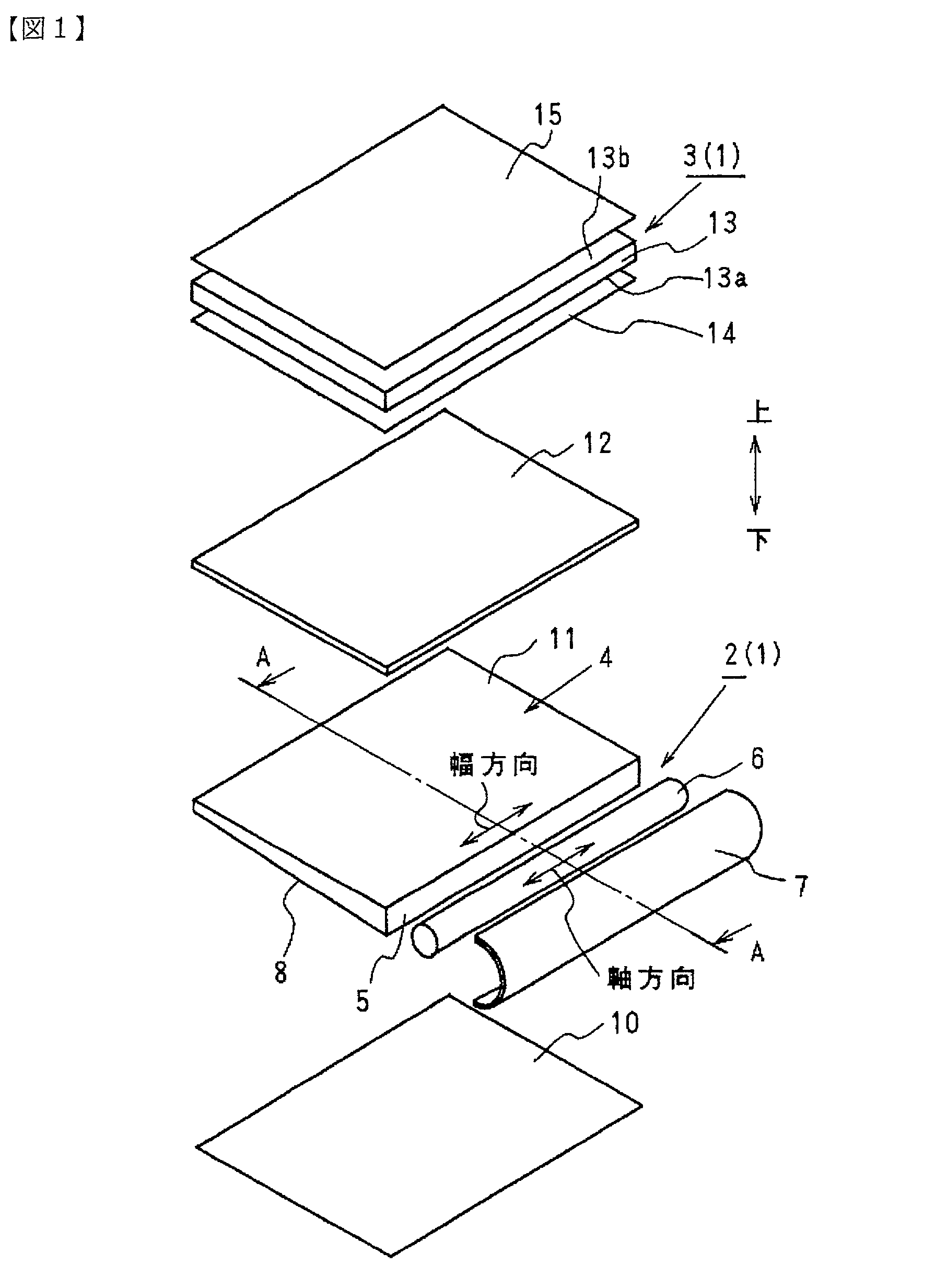
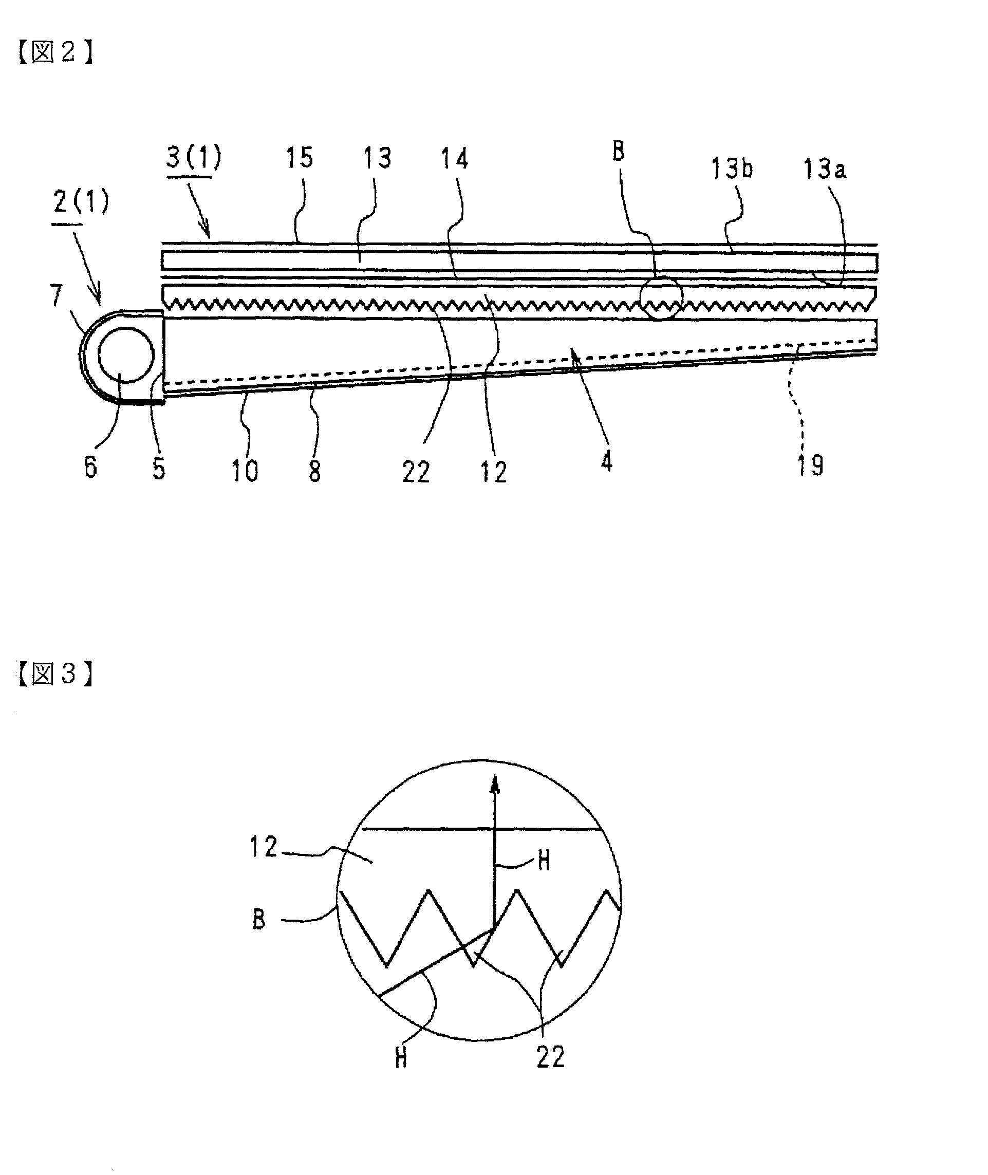
[0039] FIGS. 1 and 2 show a liquid crystal display in accordance with an embodiment of the present invention. The liquid crystal display 1 comprises a liquid crystal display panel 3 and a surface light source device 2 arranged for illuminating the panel. And the surface light source device 2 is provided with a light guide plate 4, rod-like fluorescent lamp 6, roughly-U-shaped lamp reflector 7, reflection sheet 10 and prism sheet 12.

[0040] The light guide plate 4 is rectangular and has a size roughly the same as that of the liquid crystal display panel 3. The rod-like fluorescent lamp 6 and roughly-U-shaped lamp reflector 7 compose a primary light source. The reflection sheet 10 is disposed along a back face 8 of the light guide plate 4. The prism sheet 12 functions as a light control sheet which controls and modifies direction of emission from an emission face 11 of the light guide plate 4.

[0041] The liquid crystal display panel 3 comprises a liquid crystal cell ...


PUM


Abstract

A fluorescent lamp 6 emits illumination light (primary light), which is deflected by means of a light guide plate 4 to be converted into a light flux having an enlarged cross section. A liquid crystal display panel 3 is supplied with the light flux via a prism sheet (light control sheet) 12. The prism sheet 12 or an alternative light control sheet to be employed is capable of rotating polarization involved by the light toward a direction of light transmission axis of a polarization plate 14. An effective light input to the liquid crystal display panel 3 is achieved by light transmission through the polarization plate 14 at a high transmission rate. The liquid crystal display panel 3 controls polarization state of the inputted light and, according to the state, causes the light to pass through another polarization plate (analyser) 15. Emission occurs, under intensity control depending on positions, via the polarization plate (analyzer) 15, to provide an image. Polarization rotation function for modifying the emission of the light guide plate 4 can be obtained through manufacturing of a mother material of the prism sheet 12 by means of one-axle drawing process or two-axle drawing process. Prism cuts may be formed on a back face 8 or emission face 11 of the light guide plate 4. A polarization-rotating sheet may be alternatively interposed between a prism sheet provided with no polarization-rotating ability and the polarization plate 14.

Description

[0001] 1. Field of the Invention[0002] The present invention relates to a surface light source device, a liquid crystal display employing the surface light source device and a light control sheet which is advantageously applied to them. The present invention is applied, for example, to displays for personal computer or navigation system.[0003] 2. Related Art[0004] Referring to FIG. 16, shown is an outlined arrangement of a liquid crystal display 29 which is employed, for example, in a portable personal computer. The liquid crystal display 29 comprises a liquid crystal display panel 32 and a surface light source device 33 disposed on a lower side (i.e. back side) of the panel. The illustrated surface light source device 33 is provided with a fluorescent lamp 36, light guide plate 34 and prism sheet (light control sheet) 35.[0005] According to a well-known operation, the fluorescent lamp 36 emits illumination light (primary light), which is deflected by the light guide 34 to be conver...

Claims


Application Information

Patent Timeline
IPC IPC(8): G09F9/00F21V8/00G02B5/04G02B6/00G02F1/1335G02F1/13357
CPCG02B6/0038G02B6/0046G02B6/0056G02B6/0065G02B6/0071G02F1/13362G02F2001/133507G02F2001/133607G02F1/133507G02F1/133607G02F1/1335
Inventor HIRAISHI, FUMINORI
Owner ENPLAS CORP
Why Eureka
Try Eureka