Baffle mechanism for I.S. machine

a technology of i.s. machines and baffle mechanisms, which is applied in the direction of glass blowing apparatuses, inorganic chemistry, glass shaping apparatuses, etc., to achieve the effect of improving the pneumatic operation of the baffl

Inactive Publication Date: 2001-07-12
EMHART GLASS SA
View PDF0 Cites 6 Cited by
  • Summary
  • Abstract
  • Description
  • Claims
  • Application Information

AI Technical Summary

Problems solved by technology

Bottles made in this way have a visible circular ridge on the bottom of the bottle and this is undesirable.

Method used


Image

  • Baffle mechanism for I.S. machine
  • Baffle mechanism for I.S. machine

Examples


Embodiment Construction

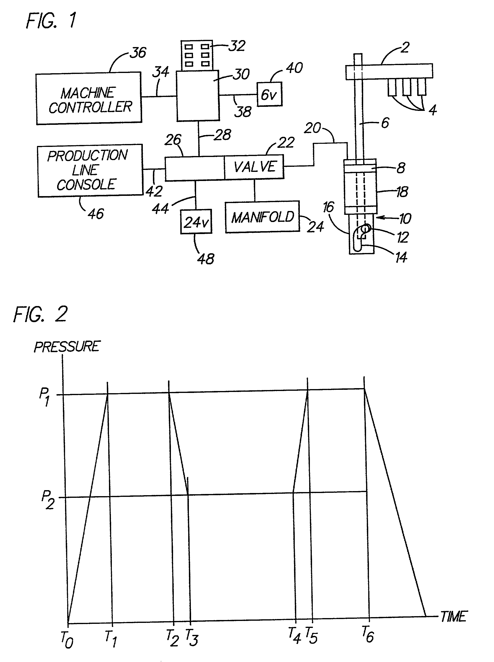
[0014] FIG. 1 shows schematically a pneumatically operated baffle mechanism for use in a section of an I.S. machine. A carrier arm 2 that supports three baffles 4 (a triple gob machine) is connected to a vertical actuating rod 6. The actuating rod 6 has attached to it a piston 8 and the actuating rod extends downwardly through the piston into a cam housing 10. The lower end of the actuating rod 6 includes a cam follower 12, in the form of a roller, which rides in a barrel cam 14 defined in the wall 16 of the cam housing 10. This actuating rod will be elevated and rotated during the uppermost portion of its elevation so that the baffle arm can be displaced between an elevated retracted position away from the center of the blank molds and a lowered advanced position where the axes of the blank molds will be coaxial with the axes of the closed blank molds and will be located on top of the blank molds. A pipe 20, which represents cylinder down air, leads from the cylinder 18 to a manifo...


PUM

PropertyMeasurementUnit
pressureaaaaaaaaaa
pressureaaaaaaaaaa
gravityaaaaaaaaaa

Abstract

An I.S. machine has a blankmold which is open at the top and includes inner and outer annular top sealing surfaces. Associated with the blankmold is a baffle including a body having a cup shaped portion closed with a vertical cylindrical bore open at the bottom, an annular bottom sealing surface for sealingly engaging the blankmold outer annular top sealing surface, and a top having a hole. A tubular sleeve communicates with the hole and extends vertically upwardly from the top of the body. A piston has a cylindrical head including a top surface, a cylindrical sealing surface and an annular bottom sealing surface having a plurality of radial notch means across the bottom thereof. A tubular rod extends vertically upwardly from the top surface for slidable displacement in the tubular sleeve, and a collar is secured to the top of the rod. A spring located between the collar and the cup shaped portion urges the cylindrical head vertically upwardly to a position whereat the cylindrical head top surface engages the top of the cup shaped portion. The collar is pneumatically displaced vertically downwardly at a high pressure to bring the cup shaped portion annular surface into sealing engagement with the blankmold outer annular sealing surface. The pressure is then reduced so that a predetermined distance separates the cylindrical head annular bottom sealing surface and the blankmold inner annular sealing surface so that settle air can be introduced into the mold, and then the pressure is again raised to the high pressure for parison formation.

Description

[0001] The present invention relates to machinery for manufacturing glass containers, such as an I.S. (individual section) machine, and more specifically to a baffle mechanism for that machine which closes the open top of a blank mold at the blank station to define an escape path for air within the mold during parison formation.[0002] This application is a continuation-in-part of Ser. No. 08 / 965,673, filed Nov. 6, 1997.[0003] An I.S. (individual section) machine has a plurality of identical sections (a section frame in which and on which are mounted a number of section mechanisms) each of which has a blank station which receives one or more gobs of molten glass and forms them into parisons having a threaded opening at the bottom (the finish) and a blow station which receives the parisons and forms them into bottles standing upright with the finish at the top. An invert and neck ring holder mechanism which includes an opposed pair of arms, rotatable about an invert axis, carries the ...

Claims


Application Information

Patent Timeline
Patent Type & Authority Applications(United States)
IPC IPC(8): C03B9/16C03B9/36
CPCC03B9/16C03B9/165C03B9/3537C03B9/36C03B9/3627C03B9/369
Inventor FENTON, FRANK ALANGOTTLIEB, RUSSELL BRUCE
Owner EMHART GLASS SA
Why Eureka
Try Eureka