Packaging and dispensing device including a vacuum-filled container, and a method of manufacture

a technology of packaging and dispensing device and vacuum-filled container, which is applied in the direction of liquid handling, packaged goods type, instruments, etc., can solve the problems of device complexity, deformation of the discharge channel of the dispenser endpiece, and deformation of the discharge channel, so as to increase the number of ways in which the pump can be used

Inactive Publication Date: 2001-08-09
LOREAL SA
View PDF0 Cites 23 Cited by
  • Summary
  • Abstract
  • Description
  • Claims
  • Application Information

AI Technical Summary

Benefits of technology

[0017] By means of the invention, the dispenser endpiece therefore remains substantially free of substance during storage, and any risk of dirtying, degradation, or drying of the substance is avoided.
[0018] In other words, the invention makes it possible to avoid untimely dispensing of a small quantity of substance when the dispenser endpiece is put into place on the control rod(s).
[0020] The invention is also advantageous when the dispenser endpiece is already fixed on a control rod before the container is filled.
[0023] The anti-vacuum valve-forming means of the invention are preferably capable of providing sealed closure in any position, thereby increasing the number of ways in which the pump can be used.

Problems solved by technology

Tests have shown that when the dispenser endpiece is mounted on the control rod after the container has been vacuum-filled, pushing in the control rod causes a certain quantity of substance to be expelled, giving rise to dirtying and also running the risk of causing substance contained in the outlet channel of the dispenser endpiece to become degraded on contact with air, and possibly even to the outlet channel becoming blocked once the substance has dried.
Mounting a common dispenser endpiece on the control rods of the two pumps after the containers have been vacuum-filled would give rise to the above-mentioned drawbacks, while mounting the dispenser endpiece before the containers are filled makes the device more complicated to manufacture.

Method used


Image

  • Packaging and dispensing device including a vacuum-filled container, and a method of manufacture
  • Packaging and dispensing device including a vacuum-filled container, and a method of manufacture
  • Packaging and dispensing device including a vacuum-filled container, and a method of manufacture

Examples


Embodiment Construction

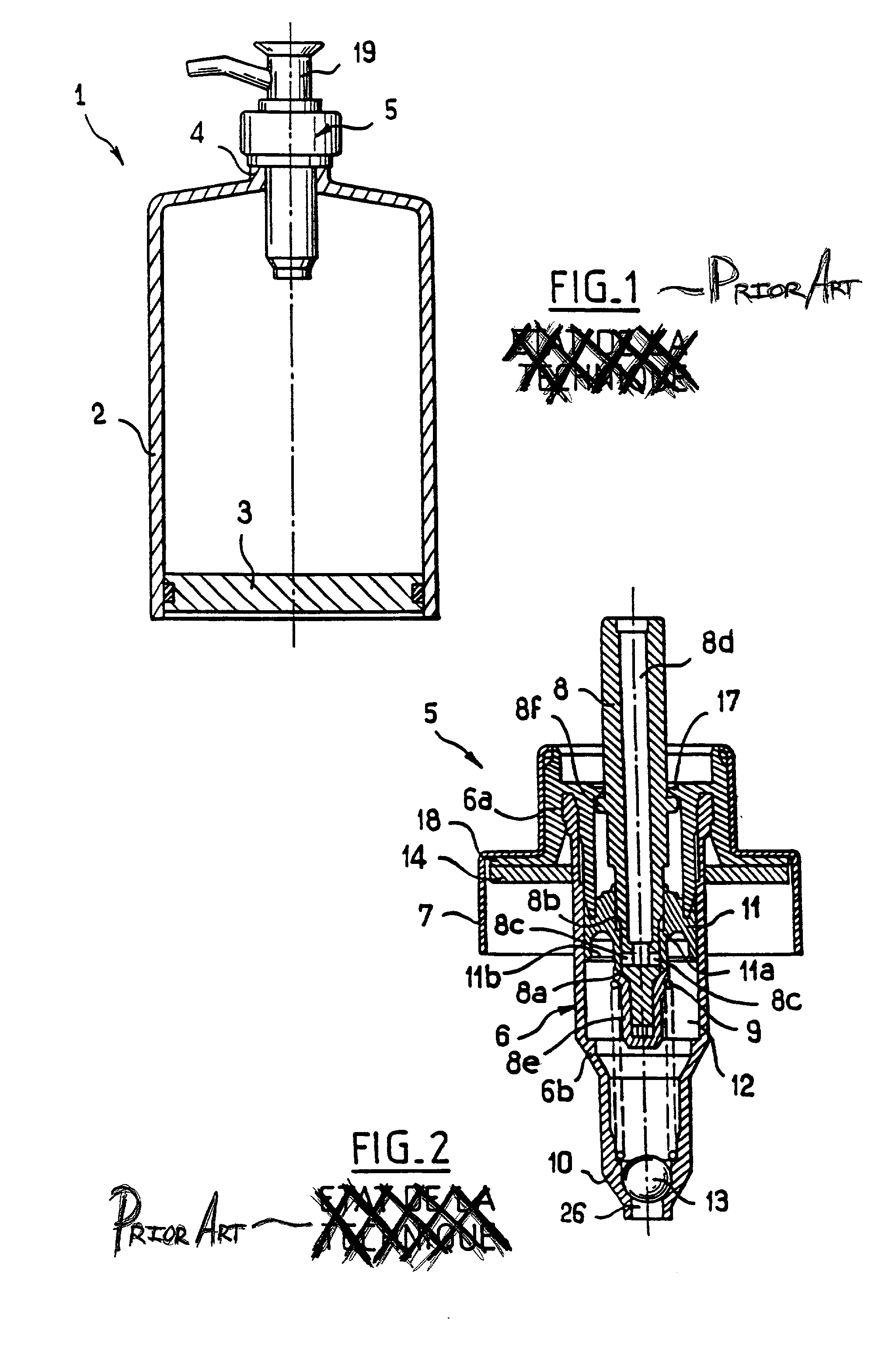
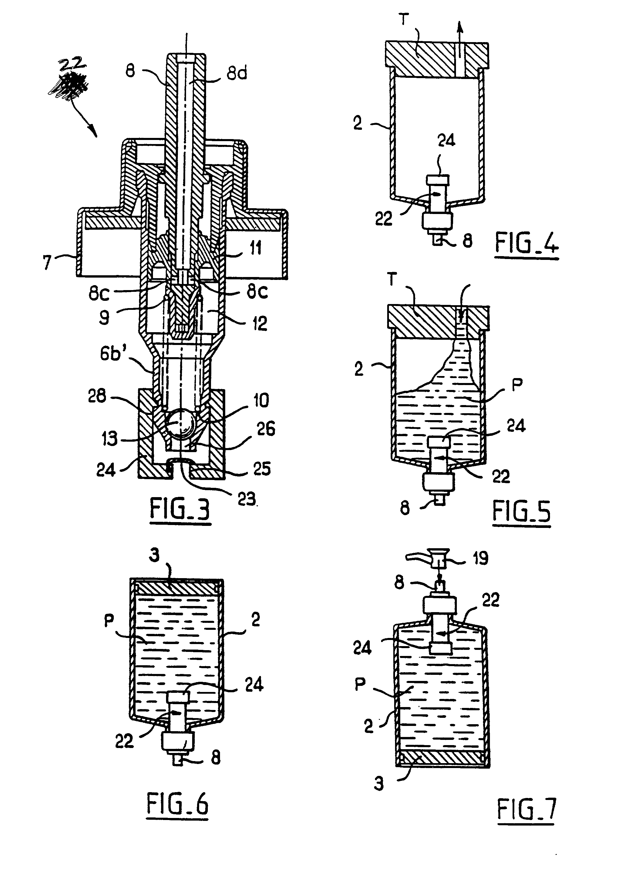
[0049] FIG. 1 shows a prior art packaging and dispensing device 1.

[0050] The device 1 comprises a container constituted by a cylindrical-walled container 2 fitted with a moving bottom constituted by a piston 3 that slides in sealed manner inside the wall 2.

[0051] The container 2 has a neck 4 at its top end on which there is fixed a pump 5 which is shown in section in FIG. 2.

[0052] The pump 5 comprises a pump body 6 constituted by snap-fastening together a top portion 6a and a bottom portion 6b.

[0053] A control rod 8 is mounted so that its bottom portion slides inside the body 6 against the action of a return spring 9 that operates in compression, one end of the spring 9 bearing against a shoulder 10 at the bottom of the bottom portion 6b of the body 6, and its other end bearing against a shoulder 8a on an endpiece 8b fixed to the bottom end of the control rod 8.

[0054] The top portion 6a has a flange 18 serving to mount the pump 5 together with a sealing ring 14 situated beneath the ...


PUM

PropertyMeasurementUnit
pressureaaaaaaaaaa
vacuumaaaaaaaaaa
volumeaaaaaaaaaa

Abstract

The invention relates to a device for packaging and dispensing at least one fluid substance. The device has at least one container filled with a substance by a vacuum-filling process, a pump associated with the container and having a pump chamber into which the substance is drawn prior to being delivered to the outside, and anti-vacuum valve-forming means organized to isolate the pump chamber(s) of the pump(s) from the inside(s) of the associated container(s) when a vacuum is established therein for filling purposes.

Description

[0001] The present invention relates to a device for packaging and dispensing at least one fluid substance.[0002] Devices are known for packaging and dispensing a fluid substance that comprise a container for containing said substance and an associated pump, the pump having a pump chamber into which the substance is taken before being delivered to the outside.[0003] The pump has intake valve-forming means and delivery valve-forming means, respectively upstream and downstream from the pump chamber. The pressure required for expelling the substance from the device is obtained by means of a control rod that is movable in the pump chamber. A dispenser endpiece, such as a pushbutton fitted with a nozzle, is fixed to the control rod before the container is filled.[0004] When a user presses on the dispenser endpiece, the control rod is pressed down into the pump body and reduces the volume of the pump chamber, causing a predetermined quantity of substance to be dispensed.[0005] When the us...

Claims


Application Information

Patent Timeline
Patent Type & Authority Applications(United States)
IPC IPC(8): B05B11/00B65B31/02B65D47/34
CPCB05B11/0043B05B11/0048B05B11/0056B05B11/0078B05B11/0097B05B11/3047B05B11/3067B05B11/026B05B11/028B05B11/1067B05B11/1047
Inventor BAILLY, CHRISTIAN
Owner LOREAL SA
Why Eureka
Try Eureka