Floating spar for supporting production risers

a technology of production risers and floating spars, which is applied in special purpose vessels, sealing/packing, and borehole/well accessories. it can solve the problems of large methods, high construction costs, and large weight of deepwater wells

Inactive Publication Date: 2001-08-16
FMC TECH INC
View PDF0 Cites 43 Cited by
  • Summary
  • Abstract
  • Description
  • Claims
  • Application Information

AI Technical Summary

Problems solved by technology

Wells for deepwater typically are very heavy given their extended length and in some cases multiple barriers where multiple concentric casing riser joints exist.
The drawback to this method is size.
If the spar's hull is larger, it is more costly to build and install, requiring more wells.
Therefore a spar may reach an economic limit, simply because the water depth and number of wells create a spar hull so large as to make it uneconomical.
The utilization of individual production risers extending from each subsea wellhead through the spar to a surface manifold and surface tree results in a substantial weight exerted on the spar particularly when multiple subsea wellheads, such as ten or more, are being utilized for product supply.
Also, a substantial space within the spar or caisson is required for the multiple lines extending through the space to the surface platform or deck.

Method used


Image

  • Floating spar for supporting production risers
  • Floating spar for supporting production risers

Examples


Embodiment Construction

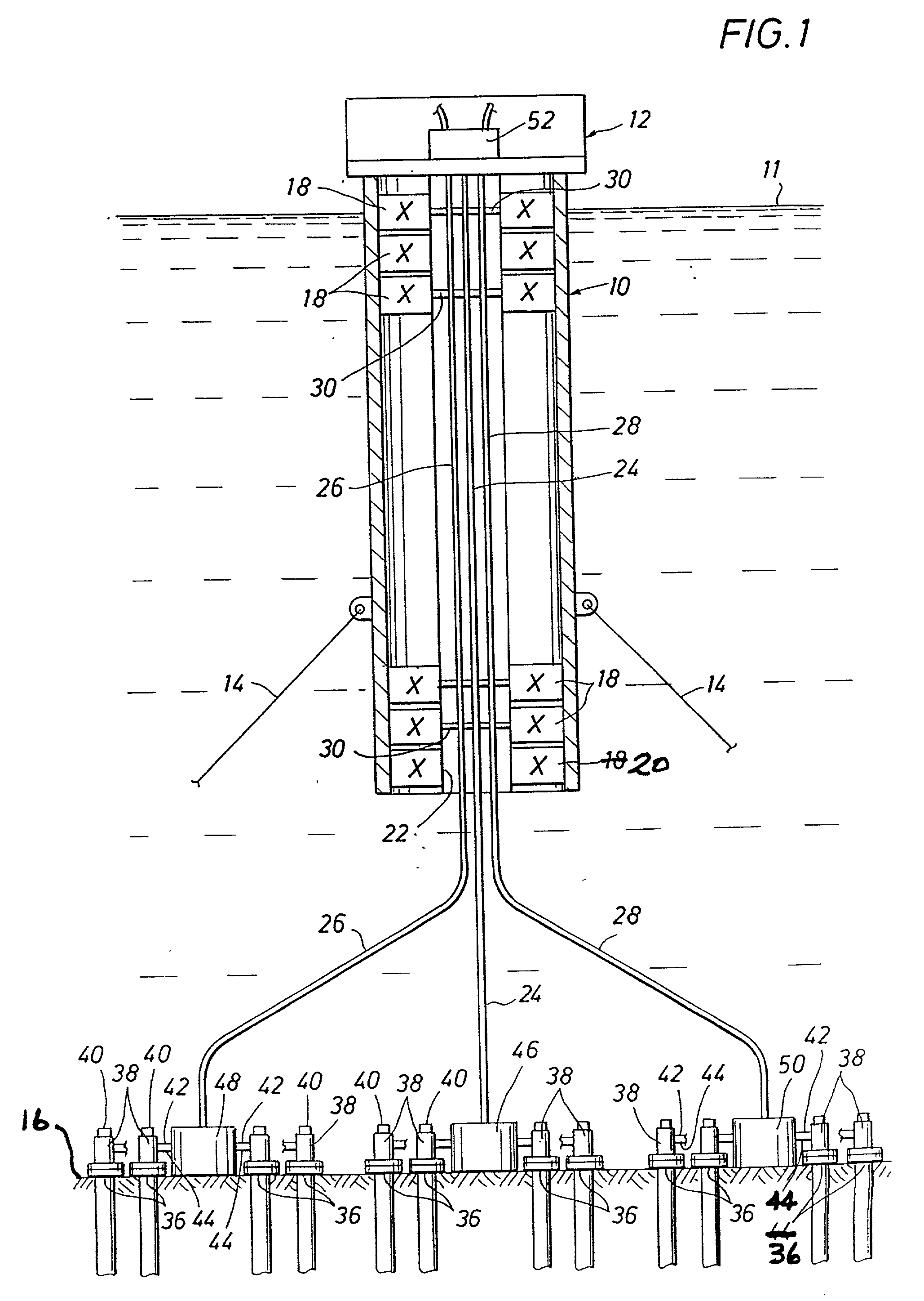
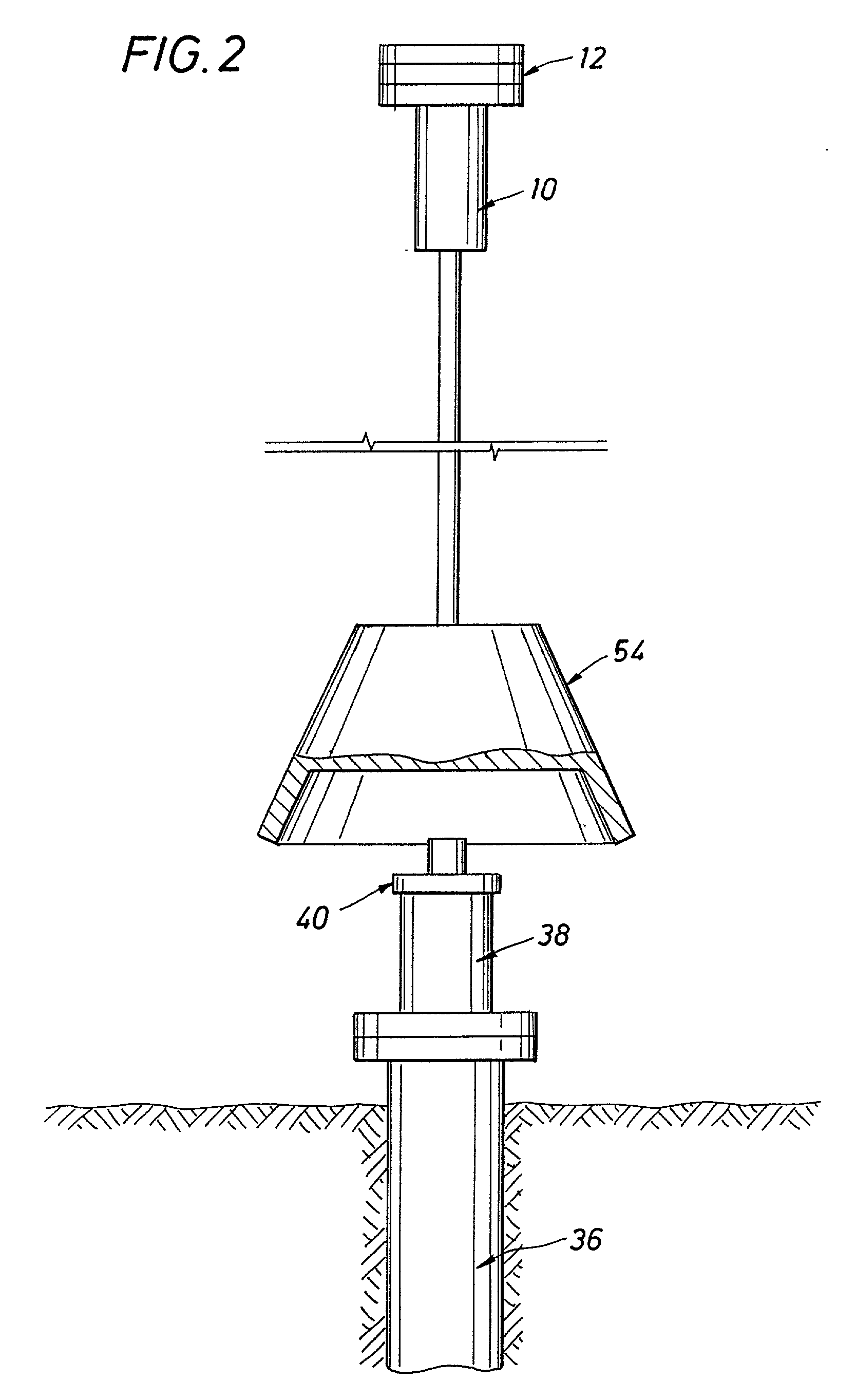
[0020] Referring to the drawings a floating spar or caisson is generally indicated at 10 having a production platform 12 with a plurality of decks mounted thereon above the sea level 11. Spar 10, for example, may be about 700 feet in length and about 75 feet in diameter, with the water depth over about 2000 feet. Mooring lines 14 are secured to anchor piles (not shown) on sea floor 16 for anchoring of spar 10. Six (6) or eight (8) mooring lines 14 are preferably utilized for mooring of spar 10. Buoys which comprise buoyancy tanks or chambers 18 are mounted within spar 10 along with ballast chambers 20. An axial bore or slot 22 is provided in spar 10 through buoyancy tanks 18 and ballast chambers 20 to receive a plurality of production risers 24, 26, 28. Test and umbilical lines may also be provided within spar 10. Suitable support members 30 on spar 10 within riser bore 22 support production risers 24, 26 and 28.

[0021] Mounted on sea floor 16 are a plurality of subsea wellheads 36. ...


PUM


Abstract

A subsea production system is provided for producing a number of subsea wells which may be arranged in groups. Each of the groups of subsea wellheads is connected to deliver production flow to a subsea manifold and each subsea manifold is connected to deliver production flow to a production riser. A plurality of production risers each being connected to receive production flow from one of said subsea manifolds extend from the subsea manifolds for groups of wells. A deep draft floating spar is located generally above the subsea wellheads with mooring lines and has a production platform located above the sea surface and has buoyancy and ballast chambers to control floatation. The spar structure defines a riser bore receiving the production risers extending from the subsea wellheads to the production platform. The spar is also capable of being shifted laterally by its mooring lines for positioning above a selected well to thus permit well intervention activities as needed. The subsea wells are each provided with wellheads having a removable cap to permit ROV actuated cap removal and replacement as needed to permit well intervention.

Description

[0001] Applicants hereby claim the benefit of United States Provisional application Ser. No. 60 / 092,354 which was filed on Jul. 10, 1998 by John A. Fitzgerald and Harold B. Skeels and entitled Floating Spar For Supporting Production Risers, which Provisional Application is incorporated herein by reference for all purposes.[0002] 1. Field of the Invention[0003] This invention relates to a floating spar for supporting a production platform, and more particularly to such a floating spar for supporting production risers extending from subsea manifolds to the production platform in deep water offshore wells.[0004] 2. Description of the Prior Art[0005] Oil and gas production spars currently utilize a number of subsea wells placed a given lateral distance on the sea floor and connected to surface facilities via individual risers where a Christmas tree is attached for well control. Wells for deepwater typically are very heavy given their extended length and in some cases multiple barriers w...

Claims


Application Information

Patent Timeline
Patent Type & Authority Applications(United States)
IPC IPC(8): B63B35/44E21B17/01E21B19/00E21B33/035E21B33/076E21B41/04E21B43/01E21B43/017
CPCB63B35/44B63B35/4406E21B17/015E21B19/004E21B33/035E21B33/076E21B41/04E21B43/01E21B43/017E21B43/0175
Inventor FITZGERALD, JOHN A.SKEELS, HAROLD B.
Owner FMC TECH INC
Why Eureka
Try Eureka