Timing signal generating device and method of generating timing signals

a timing signal and generating device technology, applied in the direction of signal generators with optical-mechanical scanning, picture reproducers using projection devices, television systems, etc., can solve the problems of increasing the price of products, business changes may be missed in same cases, etc., to achieve the effect of reducing the amount of data for control signal generation and easy chang

Inactive Publication Date: 2001-08-30
FUJIFILM CORP
View PDF0 Cites 21 Cited by
  • Summary
  • Abstract
  • Description
  • Claims
  • Application Information

AI Technical Summary

Benefits of technology

0031] The generating points of time and the signal waveforms of various kinds of timing signals adapted for driving a solid-state image pickup device can be easily changed according to specifications of apparatus using the solid-state image pickup device.
0032] The signal generation control data for controlling generation of a timing signal includes an iteration count code as above, and hence the amount of data for control signal generation can be reduced. In an electronic apparatus including an electronic device to be driven by using timing signals of a plurality of kinds, the timing signals can be generated by using a relatively small amount of data.

Problems solved by technology

However, the overflow drain pulse and the like are not always used with a repetition period of one horizontal scan period.
Even for a slight change of the hardware, the designing and fabrication of the timing signal generating device require a great expense and a long period of development and hence resultantly raises the price of the product.
Due to delay in delivery of the product, a business change may be missed in same cases.

Method used


Image

  • Timing signal generating device and method of generating timing signals
  • Timing signal generating device and method of generating timing signals
  • Timing signal generating device and method of generating timing signals

Examples


Embodiment Construction

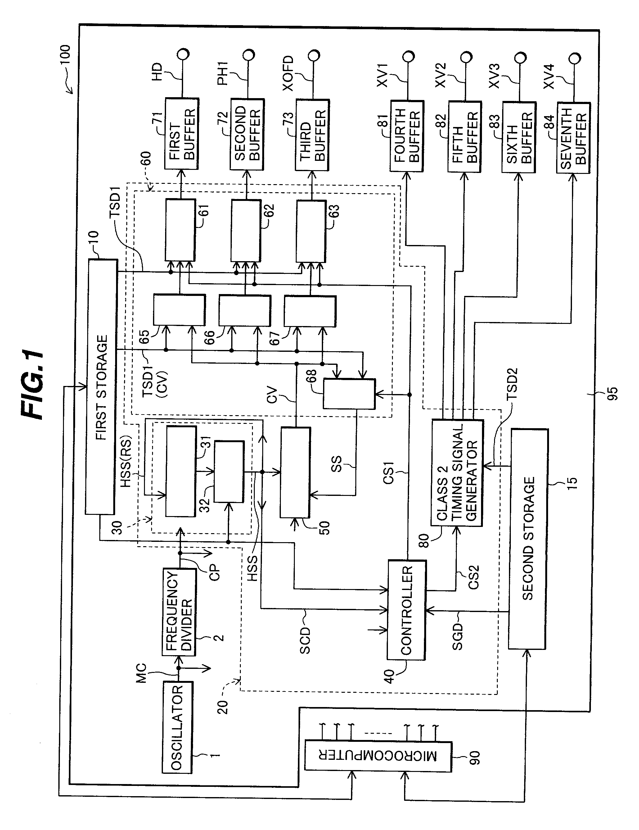
[0045] FIG. 1 illustratively shows structure of a timing signal generating device according to an embodiment.

[0046] A timing signal generating device 100 of FIG. 1 generates timing signals necessary to drive a solid-state image pickup device of CCD type used as an area image sensor.

[0047] As shown in FIG. 11, in the CCD-type solid-state image pickup device 400, a plurality of photoelectric converter elements (e.g., photo diodes) 410 are formed in a matrix shape in one surface of a semiconductor substrate 401. An actual CCD-type image-pickup device includes several hundreds of thousand of photoelectric converters elements to several million photoelectric converter elements.

[0048] For each column of photoelectric converters 410, one vertical transfer CCD (VCCD) 420 is disposed. For example, one horizontal transfer CCD (HCCD) 430 is electrically connected to each vertical transfer CCD 420. For example, an output amplifier 440 is connected to an output port of the horizontal CCD.

[0049] ...


PUM


Abstract

A timing signal generating device to drive a solid-state image pickup device including a large number of photoelectric converter elements arranged in a matrix shape, a vertical transfer path arranged for each photoelectric converter element column in the vicinity thereof, and a horizontal transfer path connected to an end section of each vertical transfer path includes at least one rewritable storage in which stored information can be rewritten by an external controller and a timing signal generating section which can generate a sequence of a plurality of kinds of timing signals corresponding to an operation mode of the solid-state image pickup device according to data stored in the storage. Therefore, generating points of time, signal waveforms, and the like of various kinds of timing signals to drive a solid-state image pickup device can be easily changed according to specifications of devices using the solid-state image pickup device as an area image sensor.

Description

[0001] This application is based on Japanese Patent Application 2000-54582 filed on Feb. 29, 2000, the entire contents of which are incorporated herein by reference.BACKGROUND OF THE INVENTION[0002] a) Field of the Invention[0003] The present invention relates to a timing signal generating device for generating a plurality of kinds of timing signals to drive a solid-state image pickup device including a large number of photoelectric converter elements arranged in a matrix shape and a method of generating the plurality of kinds of timing signals.[0004] The present invention further relates to an electronic apparatus including an electronic device driven by a plurality of kinds of timing signals, the apparatus controlling generation of the timing signals using predetermined data.[0005] b) Description of the Related Art[0006] After the technique to mass-produce charge-coupled devices (CCDs) was established, apparatus such as video cameras, digital cameras, and the like using solid-stat...

Claims


Application Information

Patent Timeline
Patent Type & Authority Applications(United States)
IPC IPC(8): H04N5/335H04N5/349H04N5/353H04N5/369H04N5/372H04N5/376
CPCH04N5/335H04N25/00H04N25/53
Inventor SUZUKI, NOBUO
Owner FUJIFILM CORP
Why Eureka
Try Eureka