Blade assembly with damping elements

a technology of damping elements and blades, which is applied in the direction of marine propulsion, vessel construction, other chemical processes, etc., can solve the problems of inability to convert vibration energy in low oscillation modes into frictional energy to a sufficient degree, and insufficient effectiveness of above damping elements

Inactive Publication Date: 2001-09-27
ALSTOM TECH LTD
View PDF0 Cites 7 Cited by
  • Summary
  • Abstract
  • Description
  • Claims
  • Application Information

AI Technical Summary

Benefits of technology

[0010] According to the invention, it has been recognized in this context that the relative movement of the faces of the damping element and of the respective blades which are in frictional contact with one another can be increased in low oscillation modes by the contact faces, contact lines or contact points with the respectively adjacent blades being selected such that they are significantly spaced apart from one another in the radial direction. As a result of this radial distance the relative movements in low oscillation modes are increased, with the result that greater energy dissipation and thus better and more effective oscillation damping can be achieved. This technology is very advantageous in particular in the case of small relative movements between adjacent blades and in low oscillation modes, such as frequently occur. However, this technology can of course also be used for satisfactorily damping relatively large relative movements or relatively high oscillation modes.
[0015] The damping elements can be used particularly advantageously if their center of gravity is located near to the first or second region. The necessary asymmetry of the damping element makes it possible to ensure that the vibration energy in the case of a relative movement between adjacent blades is converted into frictional energy in each case only at that region of contact with the damping element which is further away from the center of gravity of the damping element than the other contact region. As a result of the center of gravity of the damping element being selected to be as close as possible to one of these contact regions, there is no frictional movement, or only a very small frictional movement, at this region. This leads to an increase in the effectiveness of the conversion of energy.

Problems solved by technology

However, a disadvantage of this system is that only certain higher oscillation modes of the blade assembly are converted into frictional energy with a sufficient degree of effectiveness.
However, the resonances of rotating turbine blades which occur in practice are generally in the region of the lowest oscillation modes, so that the above damping elements are not sufficiently effective in this case.
An excessively small distance between the first and second regions leads to a situation in which the vibration energy in low oscillation modes cannot be converted into frictional energy to a sufficient degree.

Method used


Image

  • Blade assembly with damping elements
  • Blade assembly with damping elements

Examples


Embodiment Construction

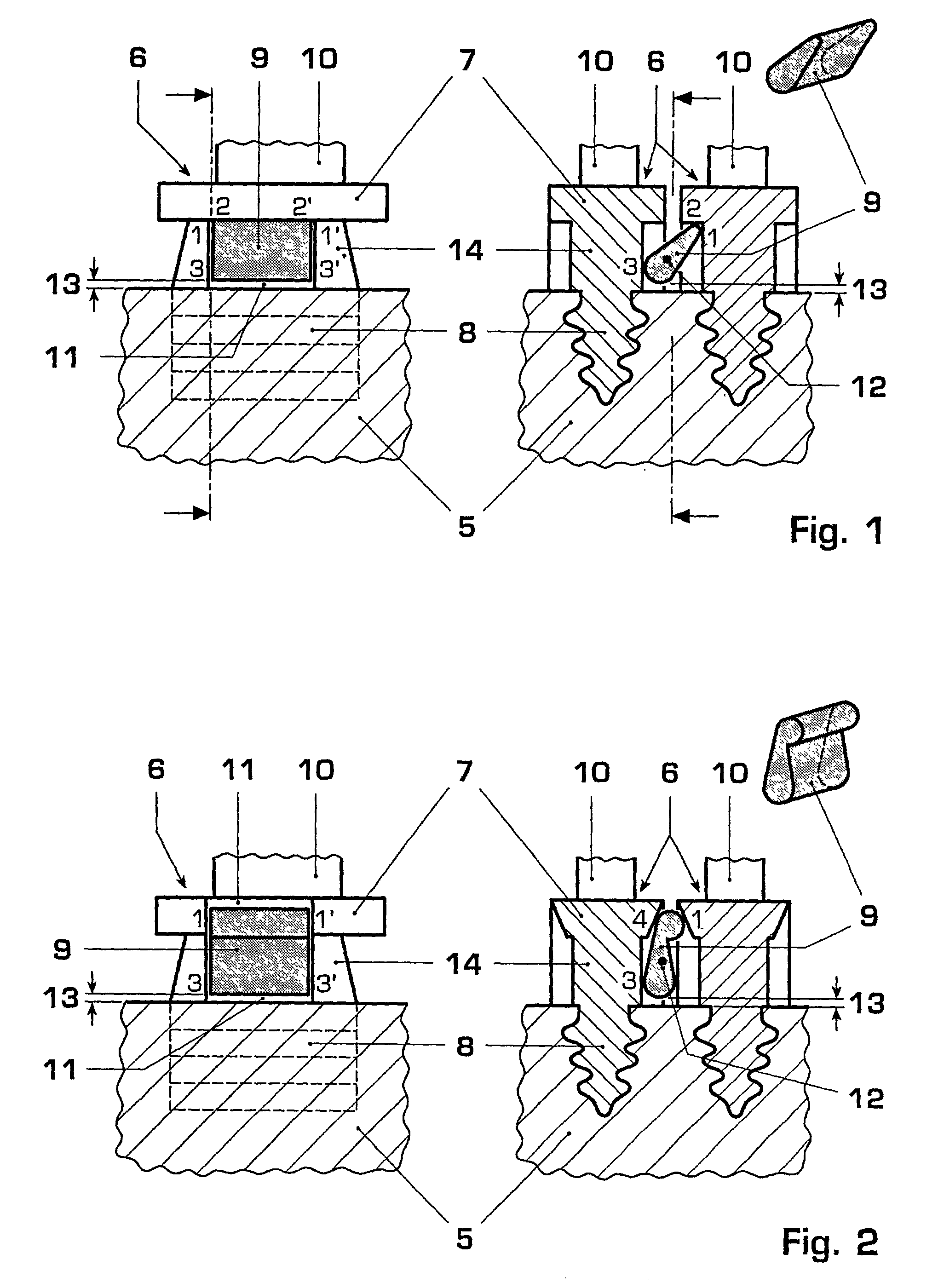
[0022] FIG. 1 shows a detail of a first example of an embodiment of the blade assembly according to the invention. A section through the blade assembly parallel to the axis of rotation is shown here in the left-hand part of the figure. The sectional plane includes the axis of rotation. In this partial view, it is possible to see the rotor 5 into which the root 8 of a blade in which the root 8 of a blade 6 s installed in a manner known per se. The shank 14 and the blade platform 7 extend between the blade element 10 (illustrated only schematically) and the rotor 5. The same arrangement is illustrated in the right-hand part of the figure in a section perpendicular to the axis of rotation, that is to say in a radial plane. A detail from the rotor 5 with two inserted blades 6 (blade i; adjacent blade i+1) with the blade platforms 7 and the shanks 14 protruding out of the rotor can also be seen here.

[0023] In this example, a damping element 9 is arranged between the adjacent blades and i...


PUM


Abstract

The present invention relates to a blade assembly with damping elements, which comprises a rotor (5) and blades (6) which are installed on the circumference of the rotor and have a blade platform (7), shank (14) and root (8). A damping element (9) is arranged between respectively adjacent blades (6), said damping element (9) being frictionally connected on rotation of the rotor (5), to at least a first region (1, 2) of a first of the respectively adjacent blades (6), and to a second region (3) of a second of the respectively adjacent blades (6). The blade assembly is characterized by the fact that the damping element (9) is configured and arranged between the first and second blades in such a way that the first region (1, 2) and the second region (3) are located at positions which are significantly spaced apart from one another in the radial direction. This blade assembly provides efficient oscillation damping even in the case of small relative movements between adjacent blades.

Description

TECHNICAL FIELD OF APPLICATION[0001] The present invention relates to a blade assembly with damping elements, which comprises a rotor and blades which are installed on the circumference of the rotor, extend in the radial direction and have a blade platform and a root. Arranged at least between a number of respectively adjacent blades is a damping element which, on rotation of the rotor, is frictionally connected to at least a first region of a first of the respectively adjacent blades, and to a second region of a second of the respectively adjacent blades.[0002] Such blade assemblies are used, in particular, in turbo-engines such as gas turbines. The individual blades are composed here of the blade element, the blade platform, the shank and the root, which is inserted into corresponding recesses on the circumference of the rotor. When the blade assembly is operating, undesired oscillations occur owing to various excitation mechanisms, and said oscillations can lead to premature mate...

Claims


Application Information

Patent Timeline
Patent Type & Authority Applications(United States)
IPC IPC(8): F01D5/22F01D25/06
CPCF01D5/22F01D25/06F05D2250/70Y10S416/50
Inventor SZWEDOWICZ, JAROSLAW
Owner ALSTOM TECH LTD
Why Eureka
Try Eureka