Gas flow control device

a flow control and gas technology, applied in the direction of sealing/packing, instruments, borehole/well accessories, etc., can solve the problems of difficult to calculate the flow rate of gas past the valve, complicating any design or examination, and reducing the unsuitable effect, so as to reduce the unsuitable effect.

Inactive Publication Date: 2001-10-04
PETROLEO BRASILEIRO SA (PETROBRAS)
View PDF7 Cites 10 Cited by
  • Summary
  • Abstract
  • Description
  • Claims
  • Application Information

AI Technical Summary

Benefits of technology

0005] This invention is of an improvement to the seat of this kind of valve, with the aid of an optimum geometric arrangement of such seat so as to render flow isoentropic within the valve, thereby greatly reducing the unsuitable effects referred to in the geometry currently adopted. This new idea consists of a so-called compact venturi which is the result of coupling a tapering nozzle to a conical diffuser. This device is almost as efficient as a regular venturi, though quite a lot shorter (a requirement as regards the valve) and much easier to make, therefore cheaper.

Problems solved by technology

Flow of gas past this gate is highly irreversible and therefore much load is lost and also it is difficult to calculate rate of flow of gas past the valve, thereby complicating any design or examination.

Method used


Image

  • Gas flow control device
  • Gas flow control device
  • Gas flow control device

Examples


Embodiment Construction

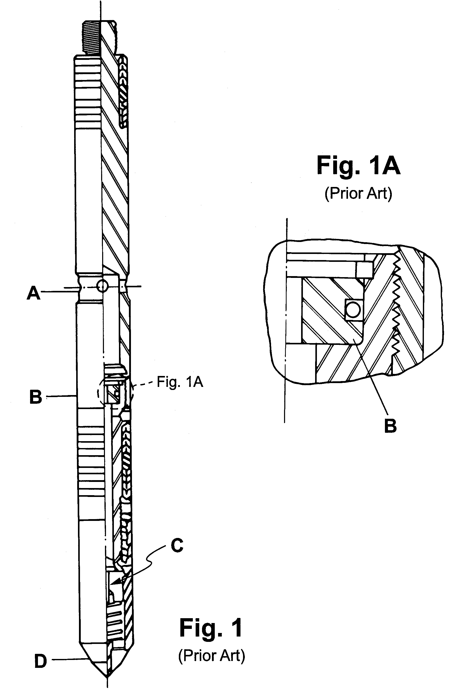
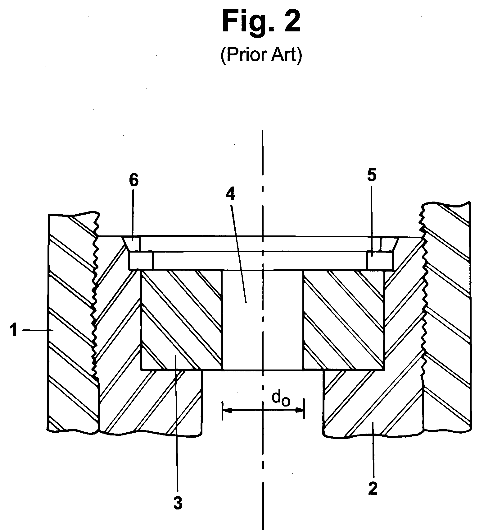
[0013] Figure 1 is a sketch of a gate valve type of gas-lift valve currently in use. In the Figure there is a point marked A where gas enters the valve, passes through the valve seat B (that is, the gate), passes check valve C and leaves out of nose D for the inside of the pipe, Figure 1 also shows a detailed view in section of the seat, shown as a sketch in Figure 2, in which the cylindrical body of valve 1 can be seen, the housing 2 for the seat, and the seat 3, the gate 4 and o ring 5.

[0014] It will be seen that seat 3 is just a disk in which a cylindrical hole of the wanted diameter has been drilled. Edges are, as a rule, sharp but they may also be slightly chamfered 6.

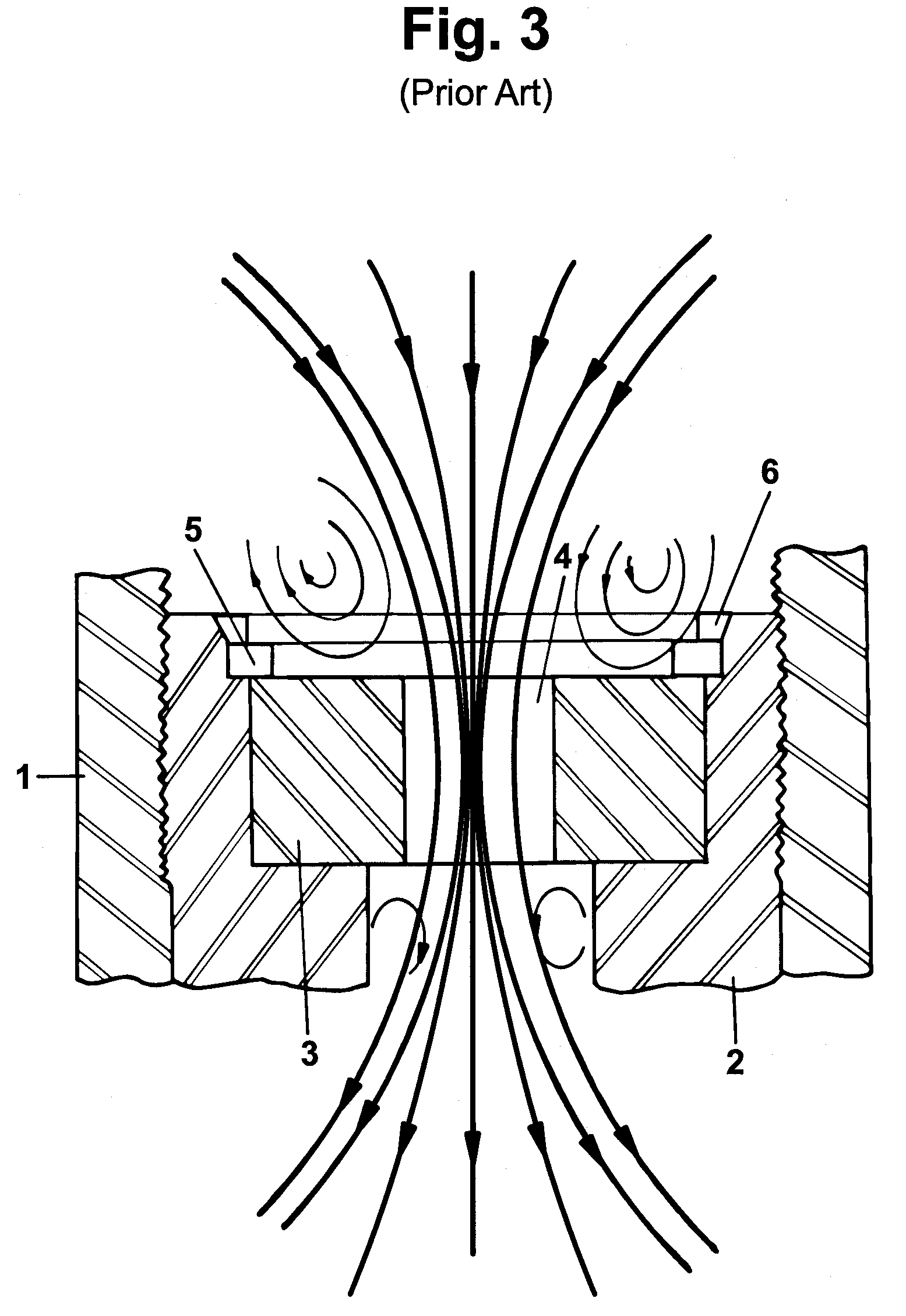
[0015] Figure 3 is a sketch of flow lines through the gate 4 as through seat 3. Sudden contracting and expanding causes swirls which bring about heavy load losses. Furthermore, the smallest area of flow does not take place along the the tight part (seat) but rather, further on, as a phenomenon known as "vena contr...


PUM


Abstract

<heading lvl="0">Abstract of Disclosure</heading> Invention is of an improvement to seat of gate valves used for gas-lift producing oil wells, consisting of a seat lower part of which is curved there being a straight vertical art and a sloping straight lower part, central spacing consisting of a first part in the shape of a tapered nozzle at which gas is gradually speeded up, a second part which is the main restriction to flow, and a third part in the shape of a conical diffuser at which gas is gradually slowed down.

Description

Cross Reference to Related Applications[0001] This is a Continuation of Application No. 08 / 186,469 filed January 26, 1994.Background of Invention[0002] The present invention is directed to a gas flow control device and more specifically to a gas flow control device for use in oil wells producing by continuous gas-lift. Such a gas flow control device is sometimes referred to in the industry as a gas-lift valve having a housing and a valve seat. The latter terminology is used throughout the specification.[0003] At wells where production is by continuous gas-lift a valve commonly used in working of the well is referred to as a gate valve. It is the valve which lets in gas from between the annulus and the production pipe, into the latter. At a given stage of well discharge production is carried out by means of this gas.[0004] Gate valves consist mainly of a gate which is preset at a given diameter, which does not change as long as the valve is within the well. Flow of gas past this gate...

Claims


Application Information

Patent Timeline
Patent Type & Authority Applications(United States)
IPC IPC(8): E21B34/06F04F1/20
CPCF04F1/20Y10T137/2934
Inventor ALMEIDA , ALCINO R.
Owner PETROLEO BRASILEIRO SA (PETROBRAS)
Why Eureka
Try Eureka