Cable/satellite/internet-ready multimedia television

Inactive Publication Date: 2001-10-04
SIMON RUDY J
View PDF21 Cites 22 Cited by
  • Summary
  • Abstract
  • Description
  • Claims
  • Application Information

AI Technical Summary

Benefits of technology

[0018] It will be understood that within the scope of the present invention, the cable signal transmission mode is capable of conveying both television signals and Internet signals. The term "television" as used herein includes reference to High Definition television (HDTV). Furthermore, as used herein, the term "cable" includes reference to coaxial cable, Composite-video cable, S-video cable, Component-video cable, and optical cable. It will be further understood that, within the scope of the present invention, the Internet may be accessed by different means including, by way of non-limiting example, Ethernet, phone line, cable, and satellite receiver. Finally, the scope of the present invention anticipates that new cable formats for television and / or video signals will be developed. Therefore, the present invention will have increased utility as these new cable formats are developed.
[0025] The television of the present invention includes a video display means. Three well-known video display means used with the present invention are cathode-ray picture tubes (CRTs), liquid crystal displays (LCDs), as well as wide screen projectors. With flat-screen televisions, such as those using LCDs, the question of where to place the various tuner boxes arises, as there is no cabinet on which to set them. Thus, one advantage of the television of the present invention is ease of use. The user of the present invention need only select a desired mode of signal transmission and a channel / URL, using only a single control panel that is integrated within the cabinet of the television and / or remote control device (or that is provided as a separate single control box in the case of a flat-screen television.) The scope of the present invention anticipates that new video display means will be developed. Therefore, the present invention will have increased utility as new video display means are developed.
[0026] The cable / satellite / Internet-ready television of the present invention further includes built-in surround-sound capability. Incorporated into the chassis are a power amplifier, a bass box, and multiple speakers that broadcast sound from various sides of the television chassis. The speakers are connected to the S-video inputs on the television chassis. Thus, the television comes set up for surround-sound, without the need to hook up additional speakers and amplifiers. A full sound control panel is integrated into the front panel of the cabinet which allows the operator to control the balance, volume or level, the bass, tremble, and effects. The surround-sound effect is achieved by a slight phase shift between the speaker outputs that creates the illusion of sound coming from several different directions, including from behind the listener. This surround-sound capability is particularly effective if the television is arranged in a corner of a room so that the sound broadcast from the rear side speakers of the television hits the walls nearby and is projected at an angle into the listening area.
[0029] The cable / satellite / Internet-ready television of the present invention, having only a single control box and single power cord, is very simple to hook up and eliminates the aesthetic drawbacks of the prior art by doing away with the numerous unsightly tuner boxes stacked on top of the television cabinet or on the floor, along with the tangle of power and connecting cords.DESCRIPTION OF THE ILLUSTRATIONS

Problems solved by technology

These external tuner boxes along with the requisite cables to connect them to the television are prone to disarray.
This process, needlessly cumbersome from the perspective of the viewer, is nevertheless the only option presently available to viewers.
The DeVilbiss device, however, does not meet today's needs in that it is not capable of receiving and handling satellite television transmissions.
As with the DeVilbiss device, the Rotzoll device is also incapable of handling satellite television transmissions.
Because the Ozaki device is essentially a stand-alone receiver box and separate from the television with which it is used, the problems associated with the above-mentioned receivers are still present, including in particular, the cumbersome nature of multiple connection cables.
One disadvantage of this Home Theater System is that two additional components must be connected to the television via connecting cables and may also require additional power cables.

Method used


Image

  • Cable/satellite/internet-ready multimedia television
  • Cable/satellite/internet-ready multimedia television
  • Cable/satellite/internet-ready multimedia television

Examples


Embodiment Construction

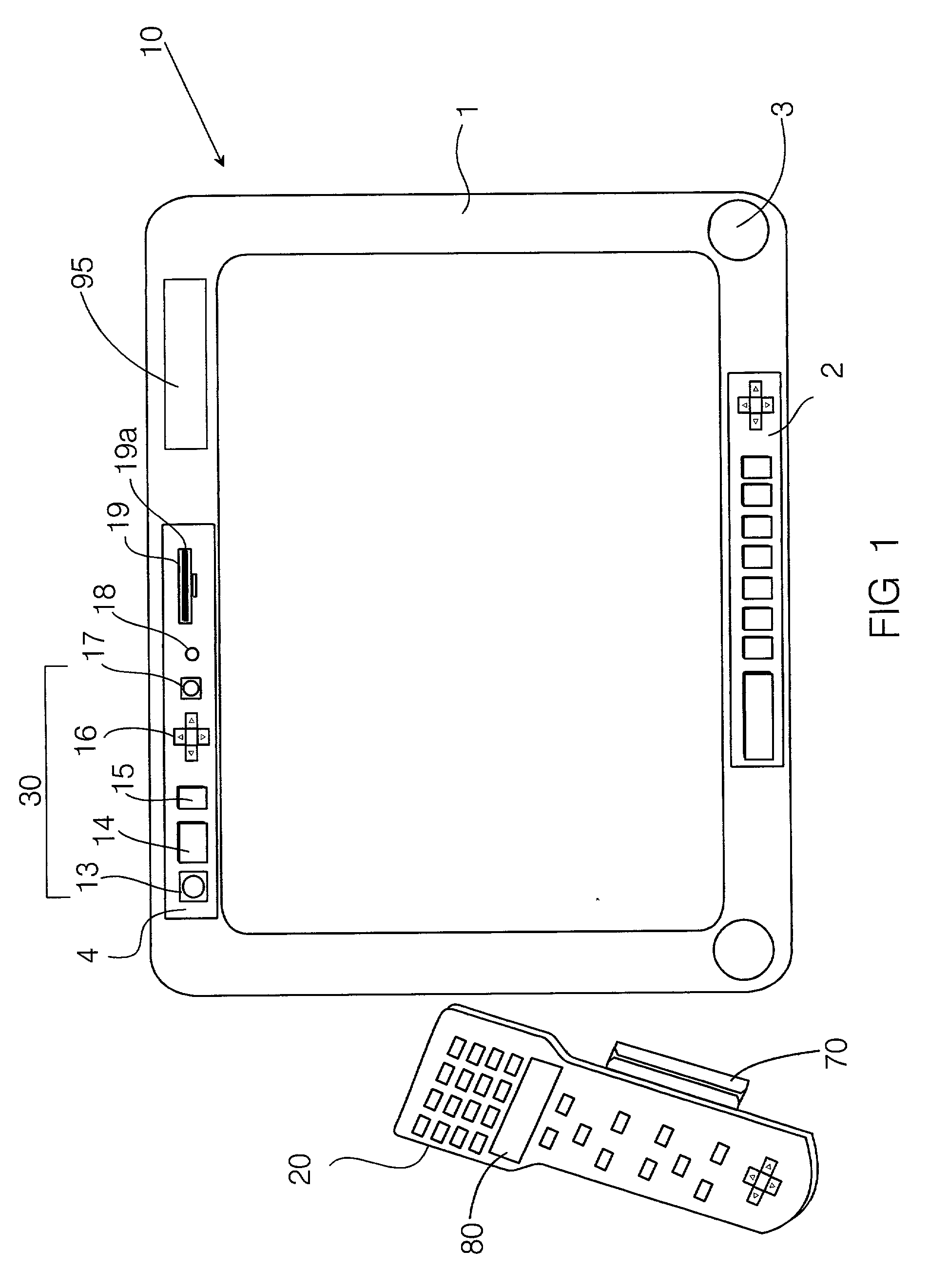
[0030] FIG. 1 is a front view of a television with remote control according to the present invention.

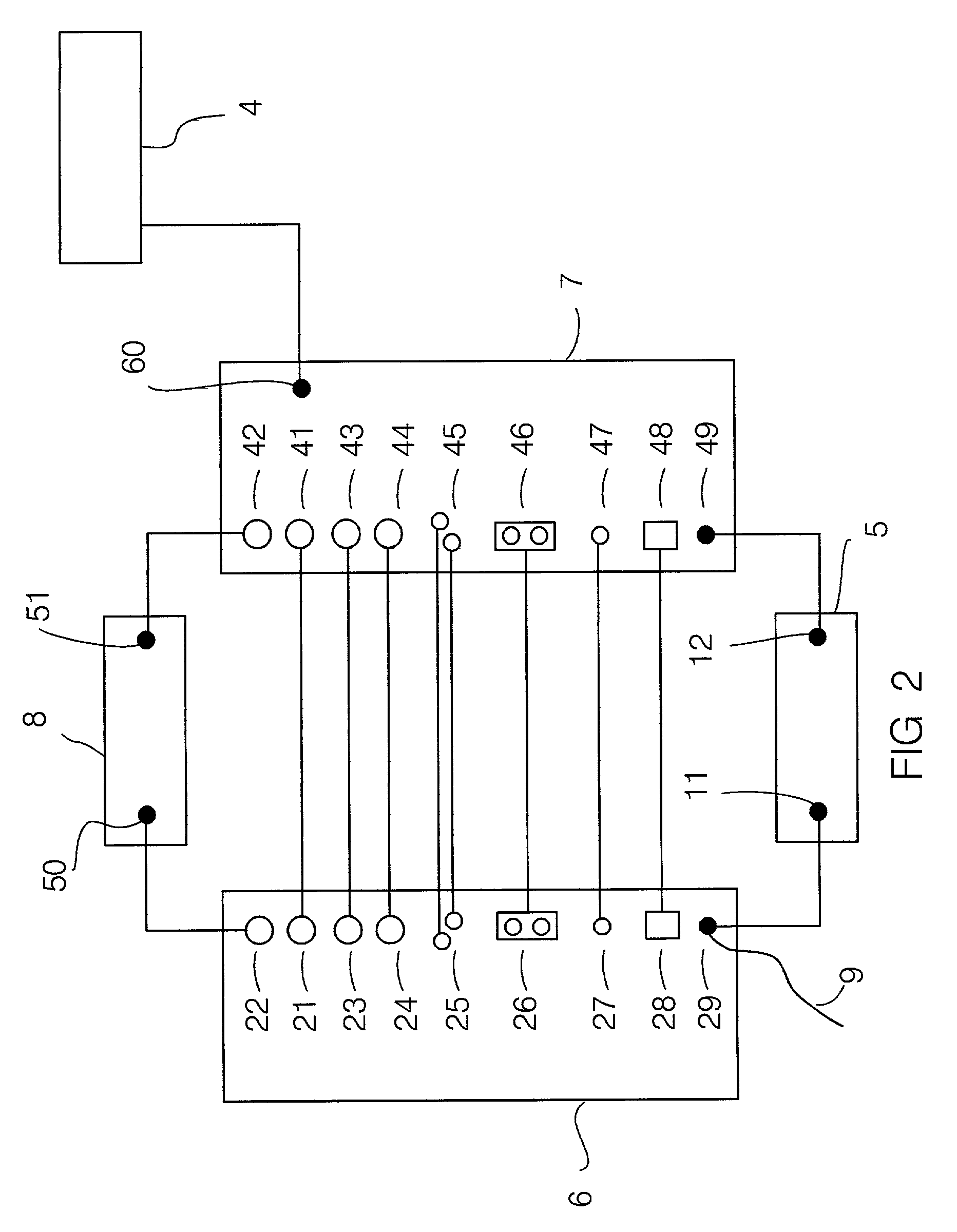
[0031] FIG. 2 is a block diagram of the main television chassis and the main satellite chassis of the present invention, showing the inputs on the main television chassis and the connections to the main satellite chassis.

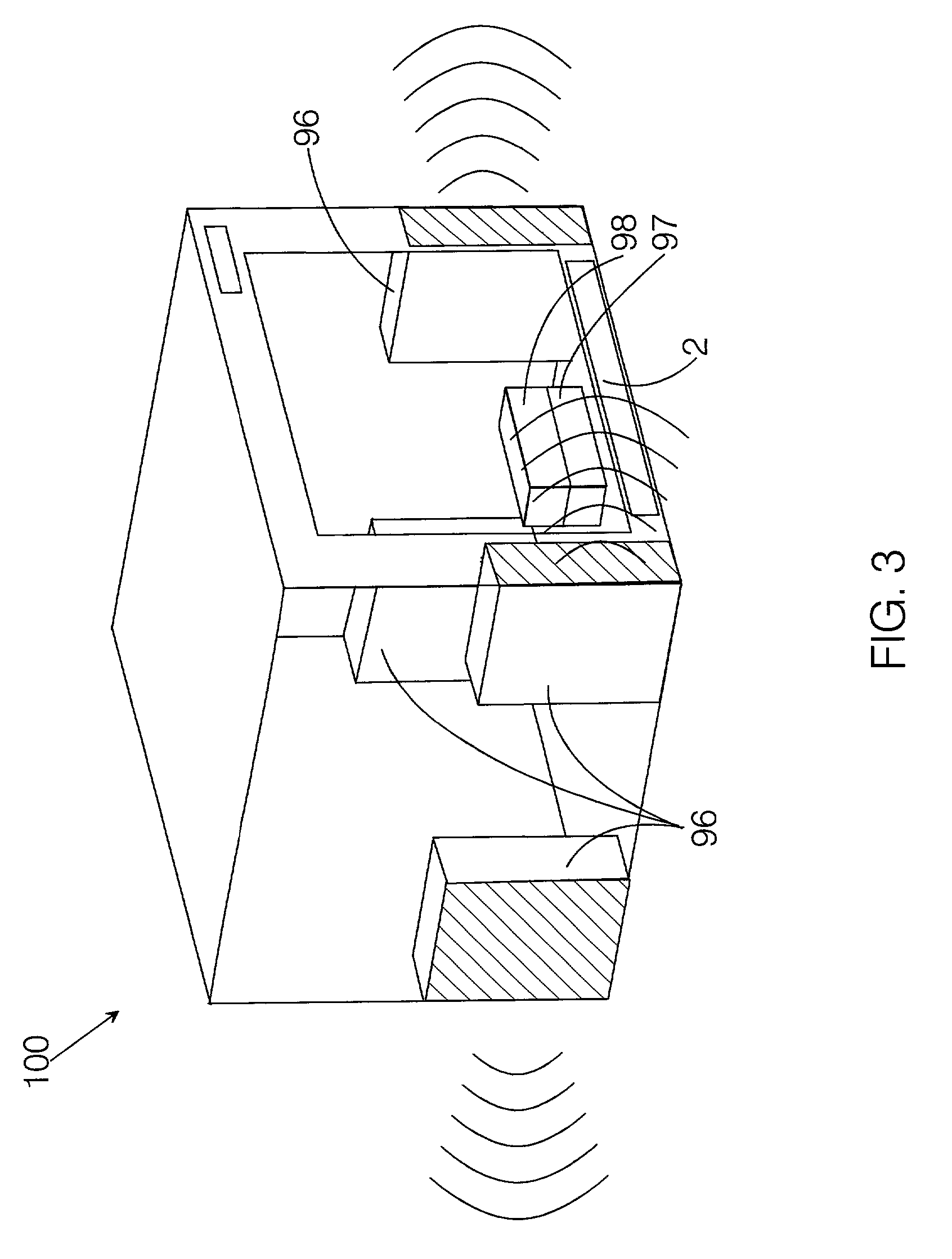
[0032] FIG. 3 illustrates the multiple speakers, the bass box, and the power amplifier integrated into the television according to the invention to provide surround-sound capability.

[0033] FIG. 4 illustrates the television with surround-sound capability, with

[0034] FIG. 5 illustrates the television according to the invention with surround-sound capability, with satellite speakers placed externally to the television.

[0035] FIG. 6 shows a television according to the invention, with multimedia devices and a computer.

DETAILED DESCRIPTION OF EMBODIMENTS OF THE INVENTION

[0036] The Preferred Embodiment of the present invention includes a cable / satellite / Internet-ready telev...


PUM


Abstract

Cable / satellite / Internet-ready television providing surround-sound, purchase-payment, and multimedia capabilities. A satellite access card slot, a wireless communication system for transmitting signals to and from a remote control device, and a surround-sound control panel are integrated into the television cabinet. A credit / debit card reader is incorporated within the cabinet or remote control device.

Description

[0001] This is a continuation-in-part of co-pending, commonly owned U.S. application Ser. No. 09 / 755,500 filed 01 / 05 / 2001, now abandoned, which is a continuation-in-part of U.S. application Ser. No. 09 / 401,579, filed 09 / 22 / 1999, U.S. Pat. No. 6,172,702.[0002] 1. Field of the Invention[0003] This invention relates to a television. More particularly, the present invention relates to a television equipped with a tuner capable of receiving television signals that are of three general classes: radio-frequency (RF) broadcast signals, signals transmitted by cable, and signals transmitted by satellite. Yet more particularly, this invention relates to such a television that is capable of being operated through the use of a single set of controls, such as on a single remote control device, and is further capable of providing surround sound, reading credit card information, and has multimedia facilities.[0004] 2. Description of Related Art[0005] At one time, television signals were radio-frequ...

Claims


Application Information

Patent Timeline
IPC IPC(8): H04N5/44H04N5/64H04N7/16
CPCH04N5/44H04N5/64H04N21/812H04N21/8586H04N21/4222H04N21/42221H04N21/42222H04N21/4223H04N21/4263H04N21/4622H04N21/47815H04N21/4782H04N21/4788H04N21/6118H04N21/6125H04N21/6143
Inventor SIMON, RUDY J.
Owner SIMON RUDY J
Why Eureka
Try Eureka