Monitoring seal system

a sealing system and sealing seal technology, applied in the direction of fluid tightness measurement, instruments, machines/engines, etc., can solve the problems of time and labor costs, the cost of accelerometers, usually three, to make vibration readings,

Inactive Publication Date: 2001-10-18
JOHN CRANE INC
View PDF0 Cites 38 Cited by
  • Summary
  • Abstract
  • Description
  • Claims
  • Application Information

AI Technical Summary

Benefits of technology

[0003] The present invention is directed to a monitoring seal system. The monitoring seal system comprises a seal housing, a seal assembly, a temperature sensor and a controller. The seal assembly sealingly engages a rotary shaft to prevent fluid leakage between the shaft and the housing. The seal assembly has at least one seal. The seal has a primary ring and a mating ring. The temperature sensor senses the temperature in the vicinity of the seal. The controller determines whether an upset condition has occurred based on at least the temperature in the vicinity of the seal.

Problems solved by technology

One problem with this procedure is the time and labor costs involved.
Another problem is the fact that the pump is not constantly monitored and so flashing (liquid to vapor transition that causes pulsating leakage and chattering of the seal) and cavitation can occur without detection.
Yet another problem is the cost of the accelerometers, usually three, required to make the vibration readings.
This expense also marshals strongly against the use of a vibration detector mounted on each pump which could monitor constantly.
Also marshalling against permanently installed vibration detectors or other detectors such as temperature and pressure detectors is the cost and effort involved in physically monitoring each detector on or near the housing, bearing or coupling and the need to constantly feed back that output to a central station or computer where the information can be viewed and utilized.
Further, the wiring for such systems is costly in time, labor and materials.
Separately, the detectors used, whether permanently installed or periodically applied by an operator, generally monitor the bearings or couplings, either directly or through the housing and do not indicate the condition of the seal, which often presages failures in other components of the pump.
Finally, the installation of such detectors often involves machining or other intrusive operations for the pumps supplied by the manufacturer.

Method used


Image

  • Monitoring seal system
  • Monitoring seal system
  • Monitoring seal system

Examples


Embodiment Construction

[0004] Other objects, features and advantages will occur to those skilled in the art from the following description of a preferred embodiment and the accompanying drawings, in which:

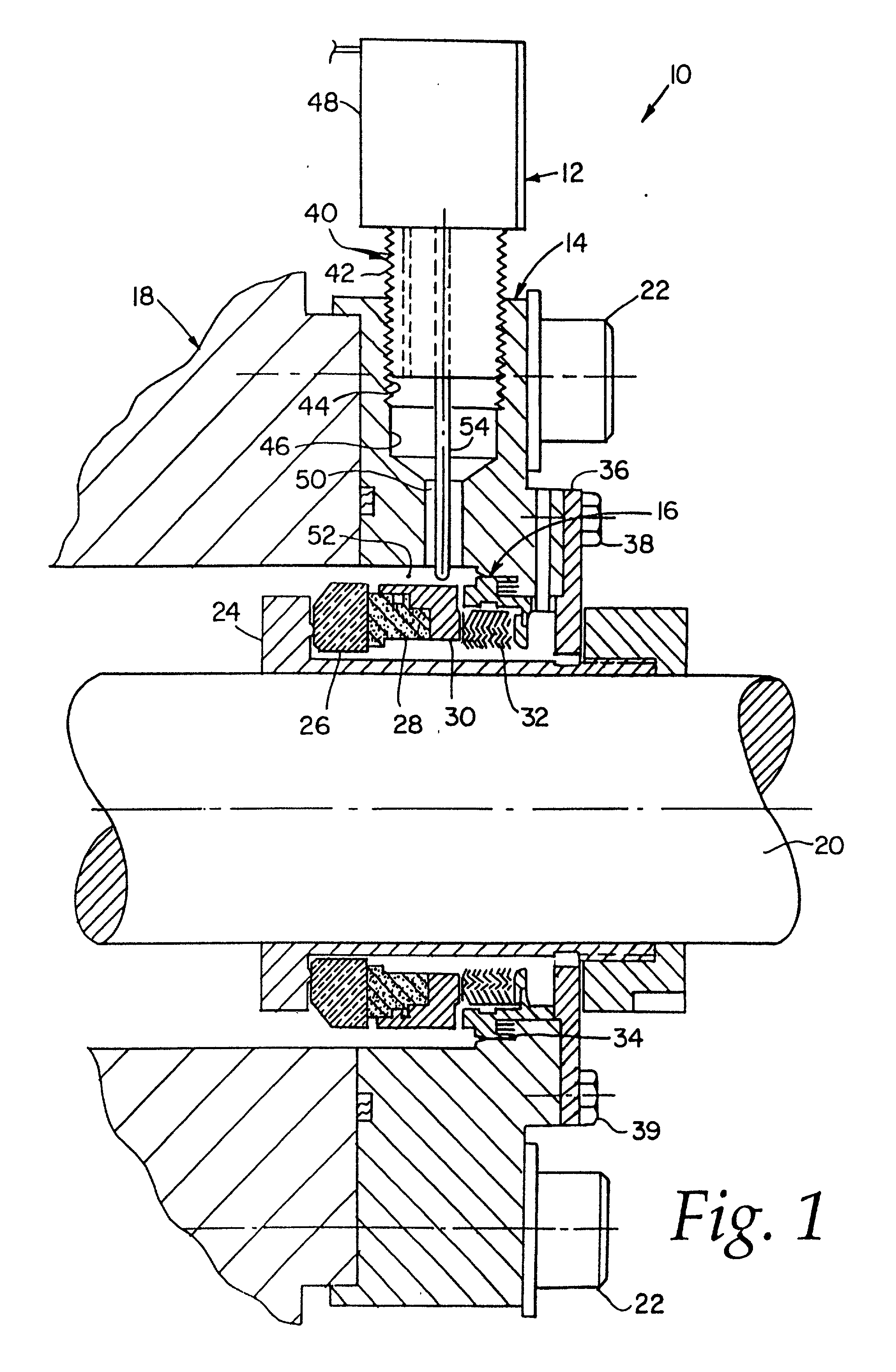
[0005] FIG. 1 is a side elevational sectional view of a rotary shaft monitoring seal system according to this invention;

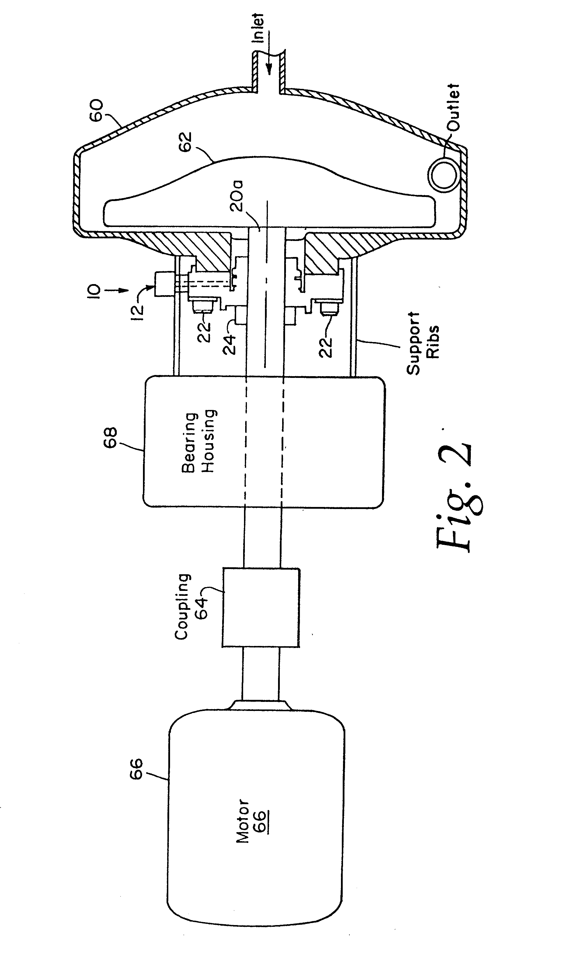
[0006] FIG. 2 is a schematic diagram showing the monitoring seal system of FIG. 1 installed between a fluid pump and its drive shaft which is driven by a motor;

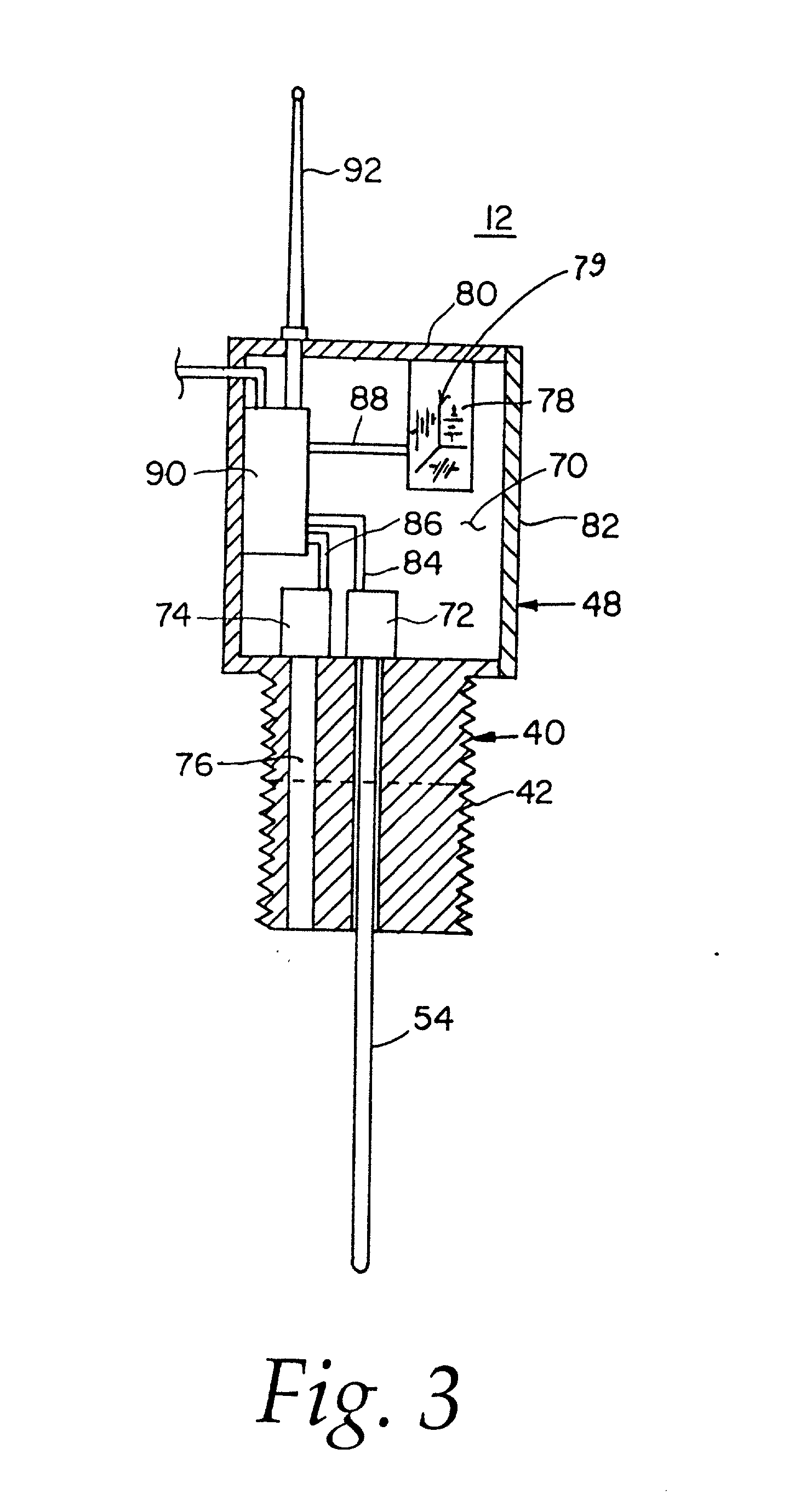
[0007] FIG. 3 is a more detailed schematic cross-sectional elevational diagram of the detector assembly of FIG. 1;

[0008] FIG. 4 is a schematic diagram showing a number of the detector assemblies of FIG. 3 in a wireless communication system with a base station served by a computer;

[0009] FIG. 5 is a side sectional view of a seal system having a number of sensors for providing data to a controller to monitor and evaluate the seal performance of a double seal assembly;

[0010] FIG. 6 is a side sectional view of a seal system having a ...


PUM


Abstract

A monitoring seal system comprises a seal housing, a seal assembly, a temperature sensor and a controller. The seal assembly sealingly engages a rotary shaft to prevent fluid leakage between the shaft and the housing. The seal assembly has at least one seal. The seal has a primary ring and a mating ring. The temperature sensor senses the temperature in the vicinity of the seal. The controller determines whether an upset condition has occurred based on at least the temperature in the vicinity of the seal.

Description

[0001] This application claims the benefits of U.S. Provisional Application No. 60 / 169,254, filed on Dec. 6, 1999. This application is also a continuation-in-part of copending U.S. application Ser. No. 09 / 606,760, filed on Jun. 29, 2000, which is a continuation of U.S. application Ser. No. 08 / 915,300, filed on Aug. 20, 1997, issued on Jul. 4, 2000 as U.S. Pat. No. 6,802,737. This invention relates to a rotary shaft monitoring seal system, and more particularly to such a monitoring seal system which monitors vibration, temperature and / or pressure at the seal location.BACKGROUND OF INVENTION[0002] Conventional pump monitoring is most often effected by a person who periodically visits each pump, makes observations of noise and leaks and takes vibration readings with instrumentation utilizing an accelerometer. The information is compared with historical data on that pump to detect trends that could result in failure of the pump bearings, couplings or seals. One problem with this procedu...

Claims


Application Information

Patent Timeline
Patent Type & Authority Applications(United States)
CPCF04C2270/90F16J15/3492G01M3/002G01M13/005
Inventor PECHT, GLENN G.WILLIAMSON, GUY GARDNER
Owner JOHN CRANE INC
Why Eureka
Try Eureka