Lead-acid safety battery cap

a safety battery and lead-acid technology, applied in the field of batteries, can solve the problems of rapid corrosion of metals, eat holes in clothing and other fabric materials, and injuring people,

Inactive Publication Date: 2001-10-18
SCHWARZ WILLIAM R
View PDF0 Cites 24 Cited by
  • Summary
  • Abstract
  • Description
  • Claims
  • Application Information

AI Technical Summary

Benefits of technology

[0019] A related object of the invention is to provide a battery cap that solves the problem of pressure buildup and envelope expansion in deep cycle lead-acid electrical storage batteries.
[0028] Preferably also the top end closure disc has a concealed inner surface facing the flame arrester and a finger projecting from the concealed inner surface toward the flame arrester. This longitudinally projecting finger resides in contact with the flame arrester when the snap fit engaging elements on the upper end of the wall and the top end closure are engaged with each other. The finger thereby serves as a means for preventing the top end closure disc from being forced too far down into the tubular body. The finger also serves to hold the porous flame arrester in position against the flame arrester seat. The flame arrester seat may be formed as an upwardly facing, annular bearing ledge by a radially inwardly extending ring shaped projection from the interior of the wall of the tubular body.
[0029] A pair of gas escape ports are located side-by-side at the same longitudinal distance along the axis of longitudinal alignment of the tubular body from the top end closure disc. The gas escape ports are located in laterally spaced separation from each other in the wall between the end closure disc and the flame arrester. The gas escape ports serve to allow gases to escape from the battery cells, thus avoiding gas pressure buildup within the battery cells.

Problems solved by technology

The sulfuric acid battery electrolyte is highly caustic and can cause injury to persons upon contact, eat holes in clothing and other fabric materials, and rapidly corrode metal if it is ejected from the battery.
Lead-acid cell batteries have intrinsic hazards.
It is well known that lead-acid storage batteries utilized on motor vehicles emit potentially explosive gases during charging and discharging.
An inherent danger that accompanies the off gassing process is the possibility that a spark, flash or flame might enter the battery cell through the vent passageway of a battery cap.
If this occurs the volatile, explosive gases are ignited within the battery, whereupon the battery will explode.
When this occurs damage to the battery compartment is very likely, and the risk of personal injury is quite great.
One problem created by porous disc spark arresters is the "loading" or destruction of the porosity of the microporous filter from suspended particulate contamination carried by the gas bubbles during off gassing.
This results in a loss of electrolyte which, when it escapes the battery, is likely to cause injury or damage.
That is, gas pressure buildup within a battery alters the outside dimensions of the battery.
The battery bulges and can damage the battery compartment.
Also, unless pressure is relieved the battery can crack and leak electrolyte.
However, until the present invention battery caps employing microporous disc spark or flame arresters have not been feasible for use with the high charge and high discharge batteries required as the sole power source for vehicles such as golf carts, warehouse forklifts and other such vehicles.
The introduction of the widespread requirement for spark and flame arresters has created a new set of problems in lead-acid electrical storage batteries.
One of these problems is the interruption of the natural equilibrium of the internal gas pressure within a battery cell and the outside atmosphere.
This imbalance in equilibrium is made progressively worse by the deterioration of the porous disc spark or flame arrester.
This deterioration results from the agglomeration of particulate contaminants in the porous disc that are carried in the aqueous electrolyte solution.

Method used


Image

  • Lead-acid safety battery cap
  • Lead-acid safety battery cap
  • Lead-acid safety battery cap

Examples


Embodiment Construction

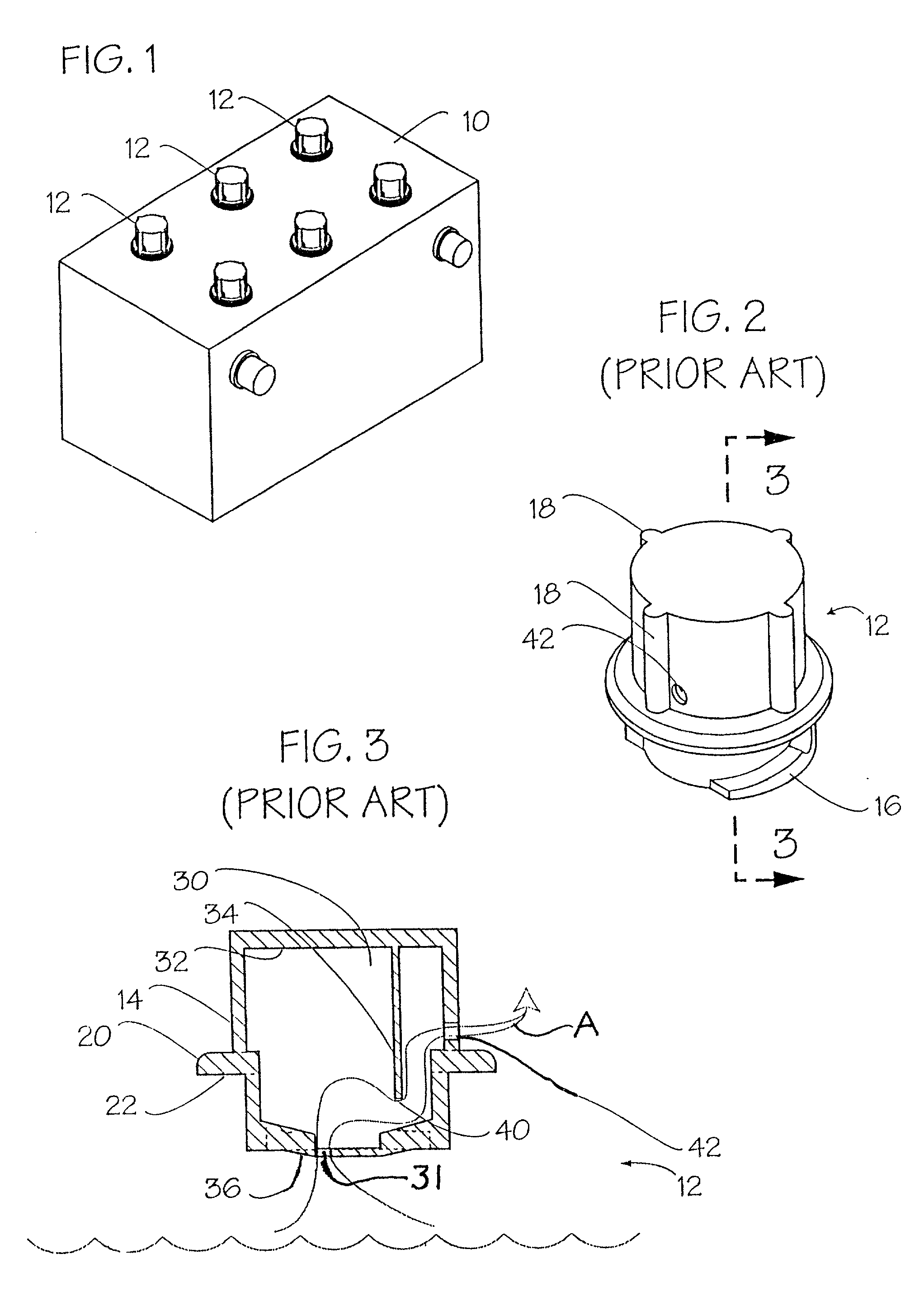
[0043] FIG. 1 illustrates a conventional, heavy duty, deep cycle lead-acid electrical storage battery 10 of the type utilized in vehicles powered solely by battery power. For example, a deep cycle battery 10 may be utilized to power a golf cart, a warehouse forklift, a wheelchair or some other mobile vehicle operated solely by battery power.

[0044] The battery 10 illustrated has six cells, each of which has a fill opening that is closed by a conventional battery cap 12. A single one of the battery caps 12 is illustrated in detail in FIGS. 2 and 3. The battery cap 12 is formed of stiff plastic that defines an upper portion of 14 and a lower portion 16. Four wings or vanes 18 spaced 90 degrees apart project radially from the otherwise cylindrical body of the upper portion 14. The wings or vanes 18 enable a user to grasp the cap 12 and twist it counterclockwise to remove it from the fill opening of a battery or clockwise to reattach it into a fill opening in the battery 10. The lower po...


PUM

PropertyMeasurementUnit
distanceaaaaaaaaaa
diameteraaaaaaaaaa
diameteraaaaaaaaaa

Abstract

A battery cap is provided for engagement in a fill port of a cell of a deep cycle, lead-acid electrical storage battery. The battery cap is formed of a hollow, tubular body having an upper end with an expansive mouth opening, and a lower end at which a transverse floor extends radially inwardly. The floor includes a central, annular convex downwardly projecting portion that defines a central fluid passage opening. The interior of the tubular wall defines a radially inwardly projecting flame arrester seat spaced from both the upper and lower ends of the body. A pair of gas escape ports are defined in the tubular wall between the flame arrester seat and the mouth opening. A diverter is located in the lower portion of the tubular body beneath a disc shaped micropore filter that serves as the flame arrester and which is seated on the flame arrester seat. The diverter is formed with a generally disc shaped, horizontal plate having diametrically opposed notches at its peripheral edge and a pair of legs of that have an arcuate cross-section and which rest upon the floor to partially surround the central opening in the floor. A battery cap having this internal structure causes drops of electrolyte to intermittently lodge in the central floor opening, thereby forming a temporary fluid seal that is repeatedly broken to allow venting of gas and reestablished to aid in protecting the micropore filter from contaminants.

Description

[0001] The present application is a continuation in part of U.S. application Ser. No. 09 / 236,453 filed Jan. 25, 1999, presently pending, which is a continuation in part of U.S. application Ser. No. 08 / 978,693 filed Nov. 26, 1997, now abandoned.[0002] 1. Field of the Invention[0003] The present invention relates to battery caps for insertion into fill ports of a lead-acid storage battery, particularly deep cycle, high charge and high discharge batteries of the type utilized on golf carts and other battery powered vehicles.[0004] 2. Description of the Prior Art[0005] A typical lead-acid battery consists of a plurality of cells filled with aqueous sulfuric acid electrolyte. The cells employ negative plates using lead as the certify that the enclosed electroactive material and positive plates in which lead oxide is the electroactive material. Sets of an equal number of positive and negative plates in the electrolyte are referred to as cells. Each lead-acid cell produces two volts per ce...

Claims


Application Information

Patent Timeline
Patent Type & Authority Applications(United States)
IPC IPC(8): H01M2/12
CPCH01M2/1211H01M2/1205Y02E60/10H01M50/308
Inventor SCHWARZ, WILLIAM R.
Owner SCHWARZ WILLIAM R
Why Eureka
Try Eureka