Machine for making bored piles

a machine and pile technology, applied in the field of borers, can solve the problems of affecting the mechanical strength of the pile, the risk of the bottom end being pulled out above, etc., and achieve the effect of high quality

Inactive Publication Date: 2001-10-25
CIE DU SOL
View PDF0 Cites 16 Cited by
  • Summary
  • Abstract
  • Description
  • Claims
  • Application Information

AI Technical Summary

Benefits of technology

0020] It will be understood that because of the presence of the annular actuator, it is possible to control the position of the bottom end of the dip tube accurately relative to the bottom end of the hollow core of the auger, thus making it possible to obtain high quality injection of concrete into the borehole as the auger and the Kelly are raised progressively, and in spite of the presence of the Kelly. In addition, using an annular actuator surrounding the dip tube makes it possible to avoid creating any axial offset between the dip tube and the assembly comprised by the Kelly and the auger.

Problems solved by technology

A major drawback of such a system lies in the way in which the concrete is introduced into the borehole in order to make the pile.
Moving this bottom end 24a by means of the carriage 18 is difficult and there is a risk of the bottom end being pulled out above the fill of concrete while the tool is being withdrawn.
Such a discontinuity is accompanied by a risk of the terrain in which the borehole has been drilled caving in locally and severely harming the mechanical strength of the pile made in this way.

Method used


Image

  • Machine for making bored piles
  • Machine for making bored piles

Examples


Embodiment Construction

[0027] A preferred embodiment of the boring machine is described, initially with reference to FIGS. 2, 3A, and 3B.

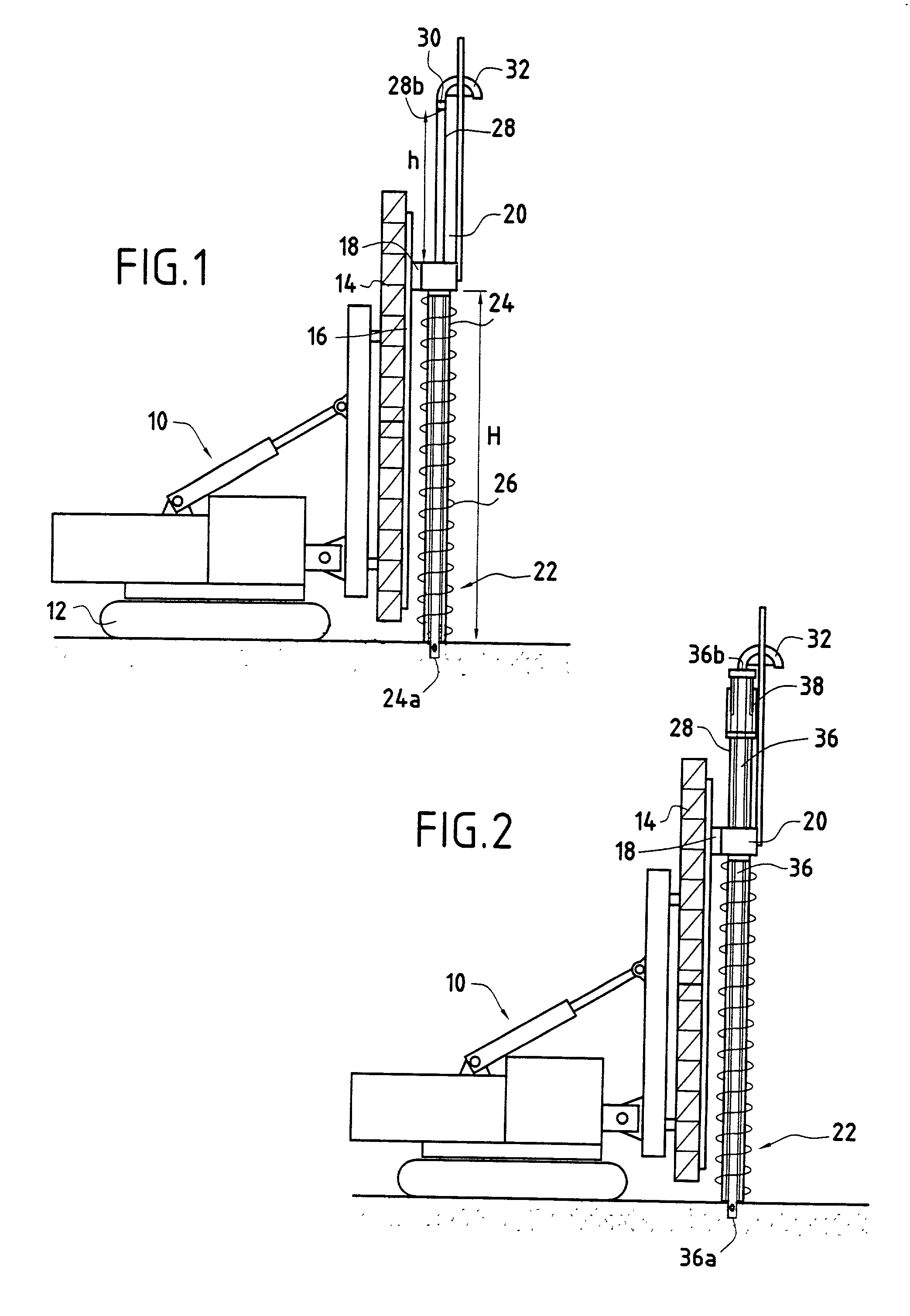
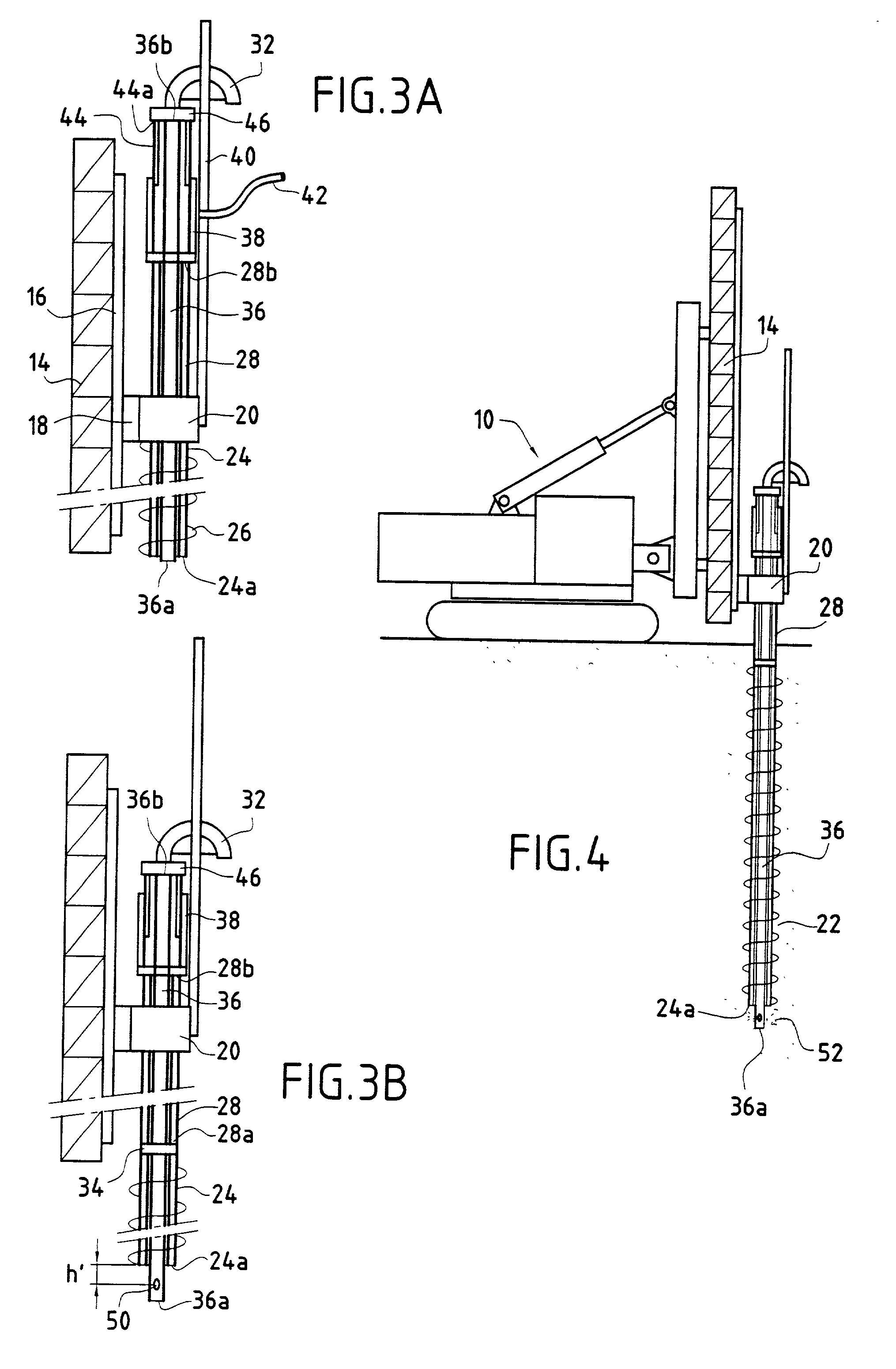
[0028] In FIG. 2, there can be seen the platform 10 with its vertical guide mast 14 having a rotary drive head 20 and a hollow auger 22 whose hollow core 24 is connected in translation and in rotation to the bottom end 28a of the Kelly 28. The mechanical connection between the core of the auger and the Kelly is of any suitable kind that enables the rotation and the translation of the rotary drive head 20 to be transmitted from the Kelly 28 to the core 24 of the auger 22. In FIG. 3B, these mechanical connection means are referenced 34.

[0029] In accordance with the invention, the machine also has a dip tube 36 which is slidably mounted in the hollow core 24 of the auger and in the Kelly 28. The dip tube 36 has a bottom end 36a and a top end 36b which is connected to the pipe 32 for feeding concrete or grout to the dip tube 36. As can be seen more clearly in FIG. 3A, the to...


PUM


Abstract

The invention relates to a machine for making bored piles. The machine comprises a vertical guide mast; a rotary drive head that is movable relative to the mast; an auger having a hollow core and at least one helical blade; an extender tube whose bottom end is secured to the top end of the auger, said drive head co-operating with said extender tube to rotate both the extender tube and the auger; a dip tube slidably mounted in the hollow core of the auger and the extender tube, the dip tube having a top end connected to a concrete feed pipe; and an annular actuator having a first end secured to the top end of said extender tube and a second end secured to the top end of said dip tube.

Description

[0001] The present invention relates to an auger type machine for making bored piles.[0002] More precisely, the invention relates to a machine capable both of boring a cylindrical excavation in the ground and of filling said excavation with grout or concrete so as to end up by defining a cast pile in the excavated ground.[0003] Accompanying FIG. 1 shows an auger type boring machine for making cast piles. The machine comprises a platform 10 which is preferably mounted on crawler tracks 12 and which has a guide mast 14 hinged thereto, which mast is vertical when in the working position. The mast 14 carries vertical slideways 16 on one of its faces to guide a carriage 18 in translation. The carriage 18 carries a rotary drive head 20 which co-operates with a hollow auger 22 constituted by a hollow core 24 and at least one helical blade 26. The rotary drive head 20 serves to rotate the auger 22, thereby causing it to dig into the ground by screw action, and thus making the borehole. Sinc...

Claims


Application Information

Patent Timeline
Patent Type & Authority Applications(United States)
IPC IPC(8): E02D7/22E02D5/34E02D5/36E02D5/46
CPCE02D5/34E02D5/36E02D5/46
Inventor SHERWOOD, DAVID
Owner CIE DU SOL
Why Eureka
Try Eureka