System for processing directional signals

a technology for processing systems and directional signals, applied in directionfinders, instruments, measurement devices, etc., can solve problems such as degrading bearing estimate accuracy, affecting the accuracy of bearing estimates, and increasing demands on flight deck members

Inactive Publication Date: 2001-11-15
L 3 COMM CORP
View PDF0 Cites 20 Cited by
  • Summary
  • Abstract
  • Description
  • Claims
  • Application Information

AI Technical Summary

Problems solved by technology

As technology in air transportation has evolved, the demands on the members of the flight deck have become increasingly severe.
Various factors, however, may degrade the accuracy of the bearing estimate.
For example, monitoring aircraft having small fuselages may detect transponder signals differently than larger

Method used


Image

  • System for processing directional signals
  • System for processing directional signals
  • System for processing directional signals

Examples


Embodiment Construction

[0021] A signal processing system according to various aspects of the present invention provides a system for calculating the bearing of a signal source, such as an intruder aircraft, which is adjusted according to various criteria, such as the size of the fuselage of the monitoring aircraft or the relative elevation angle of an intruder aircraft. Although various aspects of the invention may be used in conjunction with a variety of systems that have a directional antenna with a plurality of receiving elements, the present invention is conveniently described below in connection with a TCAS. This exemplary implementation, however, should in no way be construed to limit the applicability of various aspects of the invention in other environments or otherwise limit the claims.

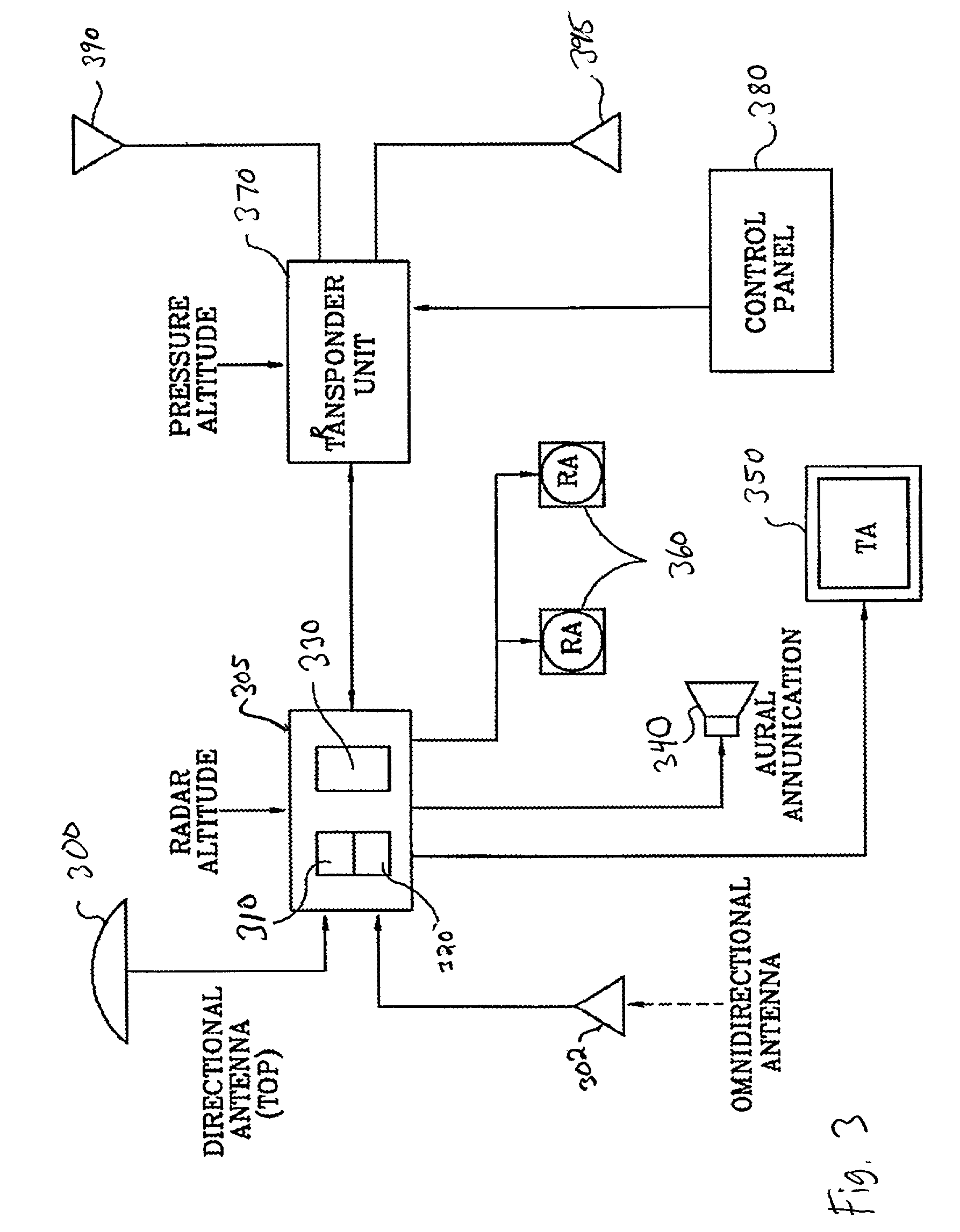
[0022] FIG. 3 is a block diagram of a conventional TCAS comprising a TCAS directional antenna 300, a TCAS omnidirectional antenna 302, and a TCAS computer unit 305 which includes a receiver 310, a transmitter 320, ...


PUM


Abstract

A system for calculating the bearing of a signal source, with a directional antenna, provides corrections for distortion, such as due to a small fuselage of the monitoring aircraft and the elevation angle of an intruder aircraft with respect to the monitoring aircraft. A correction is applied to the bearing estimate that is based on relevant factors, such as the fuselage size and the elevation angle of the intruder aircraft. The correction can be calculated or applied through the use of a look-up table, which may be either pre-selected or selected after calculation of the elevation angle of the intruder aircraft.

Description

[0001] 1. Field of the Invention[0002] The present invention generally relates to processing signals received with a directional antenna, and more particularly, to identifying the bearing of a signal source based on signals received with a directional antenna.[0003] 2. Description of the Related Art[0004] As technology in air transportation has evolved, the demands on the members of the flight deck have become increasingly severe. To avoid flight path conflicts, the flight deck crew monitors considerable aircraft status information for multiple surrounding aircraft at a time when air traffic is dramatically increasing. Higher aircraft speeds magnify the burden by reducing the time in which the flight deck crew can respond to threatening situations.[0005] To assist the flight deck crew and enhance safety, several systems have been and are being developed. Many aircraft carry transponders (e.g., mode S, mode C, mode A) by which one aircraft can communicate to a second aircraft both it...

Claims


Application Information

Patent Timeline
IPC IPC(8): G01S1/14G01S3/02G01S3/28G01S13/933
CPCG01S3/023G01S3/28G01S13/9303G01S13/933
Inventor SMITH, MARK D.
Owner L 3 COMM CORP
Why Eureka
Try Eureka