Drive system

a technology of drive system and drive shaft, which is applied in the direction of electric propulsion mounting, machine/engine, engine starter, etc., can solve the problems of affecting the functionality of electric motor, and achieve the effect of avoiding affecting the functionality of electric machines and transferring thermal energy

Inactive Publication Date: 2001-11-22
ZF FRIEDRICHSHAFEN AG
View PDF0 Cites 18 Cited by
  • Summary
  • Abstract
  • Description
  • Claims
  • Application Information

AI Technical Summary

Benefits of technology

[0006] It is an object of the present invention to provide a drive system for a motor vehicle comprising an electric machine in which the transfer of thermal energy between the electric machine and a flywheel mass arrangement is decreased to avoid impairing the functionality of the electric machine.

Problems solved by technology

The heat from these heat sources can impair the functionality of the electric motor.

Method used


Image

  • Drive system
  • Drive system
  • Drive system

Examples


Embodiment Construction

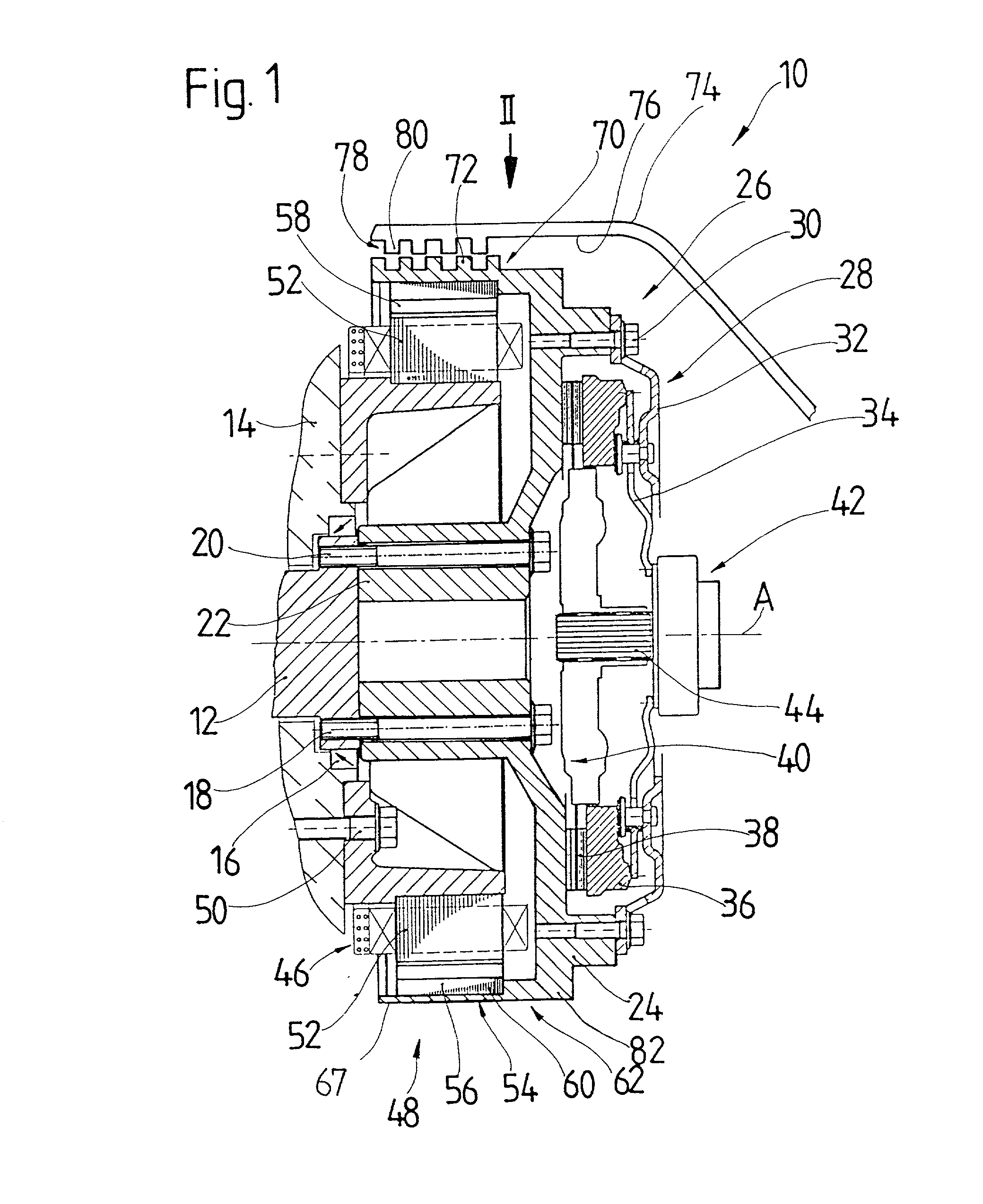
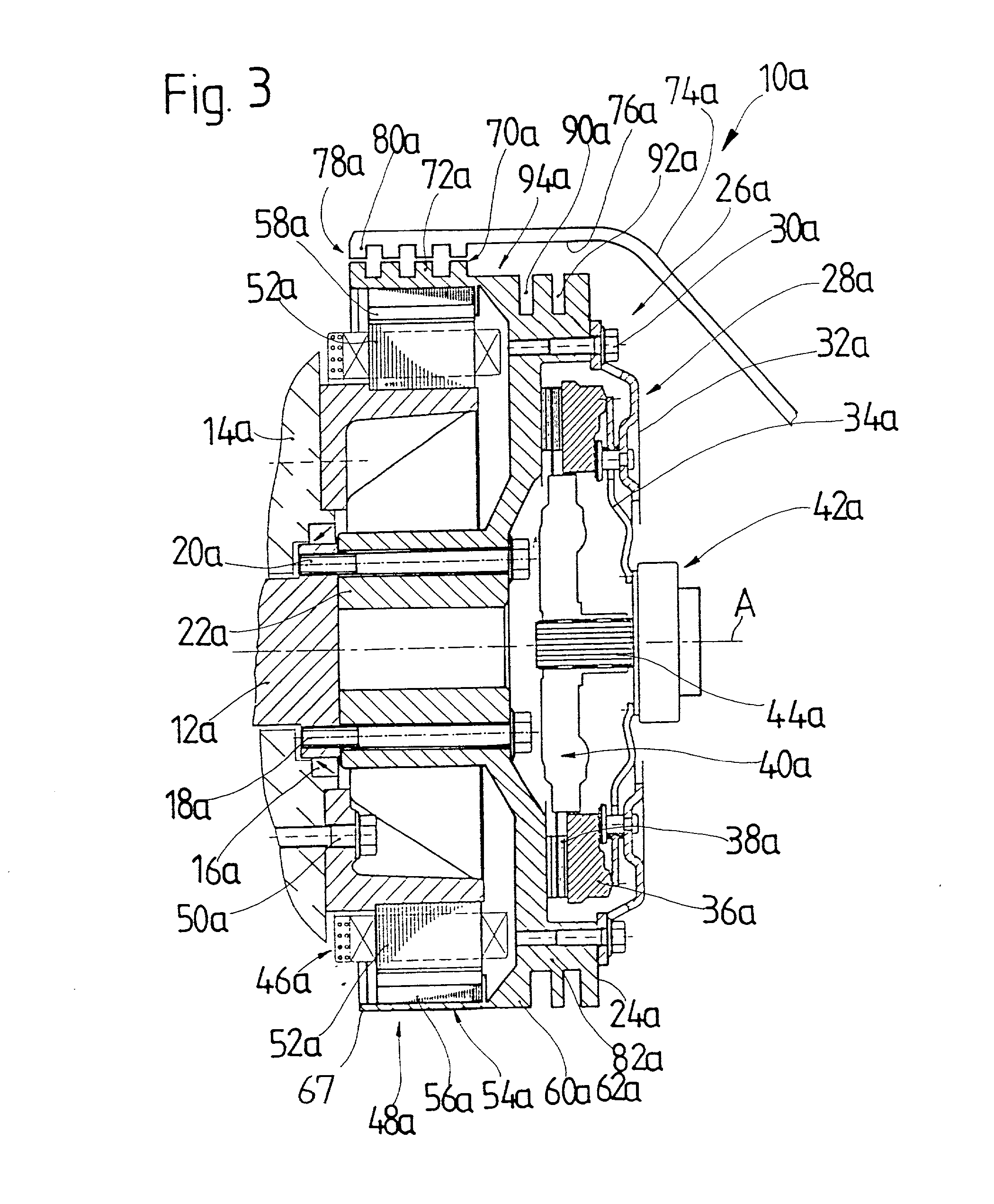
[0038] A drive system 10 according to an embodiment of the present invention is shown in FIG. 1. The drive system 10 comprises a drive shaft 12 which is rotatably mounted at the end in a crankcase 14 via a bearing 16. The drive shaft 12 may, for example, comprise a crankshaft of an internal combustion engine. A flywheel mass arrangement such as, for example, a flywheel 24 of a motor vehicle friction clutch 26 is connected in a rotationally secure fashion to a crankshaft flange 18 on the drive shaft 12 via a plurality of screw bolts 20 and a spacer element 22.

[0039] The motor vehicle friction clutch 26 comprises a pressure plate assembly 28 which includes a clutch housing 32 and a pressure plate 36 which is biased toward the flywheel 24 in the direction of an axis of rotation A under the biasing of an energy storage mechanism 34. A radially outer region of the clutch housing 32 is permanently connected by screw bolts 30 to the flywheel 24. The energy storage mechanism 34 may, for exa...


PUM


Abstract

A drive system for a motor vehicle includes a drive shaft with a flywheel mass arrangement provided thereon, an electric machine for driving the drive shaft and / or obtaining electric energy from the rotating drive shaft. The electric machine has a stator arrangement and a rotor arrangement which can be rotated by the drive shaft. The rotor arrangement is connected via the flywheel mass arrangement to the drive shaft. Furthermore, the rotor arrangement is connected to the flywheel mass arrangement via a connecting region having a higher resistance to thermal conduction than at least one of the regions that adjoins the connecting region.

Description

[0001] 1. Field of the Invention[0002] The present invention relates to a drive system for a motor vehicle comprising a drive shaft with a flywheel mass arrangement provided thereon and an electric machine connected to the shaft for rotating the drive shaft and / or for obtaining electric energy from the drive shaft, the electric machine having a stator arrangement and a rotor arrangement for rotation with the drive shaft.[0003] 2. Description of the Related Art[0004] German reference DE 196 29 346 discloses a hybrid drive system which comprises an internal combustion engine, an automatically operable clutch, an electric motor and a transmission, which are connected in series. A rotor of the electric motor is connected in a rotationally secure fashion to a transmission input shaft of the transmission with insulation regions arranged between the electric motor and the friction clutch and / or the internal combustion engine to prevent the transfer of heat to the electric motor from these ...

Claims


Application Information

Patent Timeline
Patent Type & Authority Applications(United States)
IPC IPC(8): B60K6/26F16F15/10B60K6/30B60K6/387B60K6/40B60K6/405B60K6/485B60L50/16B60L50/30F02N11/04F16F15/315H02K7/00
CPCB60K1/02B60K6/26B60K6/30B60K6/387B60K6/40B60K6/405B60K6/485B60L2270/44F02N11/04H02K7/006Y02T10/6226Y02T10/641Y10S903/903Y10S903/951Y10S903/906Y10S903/914Y10S903/952Y02T10/62Y02T10/64Y02T10/70B60K2006/268
Inventor HEYDEN, MARCUS VANTAREILUS, ALFREDWEIMER, JURGENBAUCH-PANETZKY, DIETER
Owner ZF FRIEDRICHSHAFEN AG
Why Eureka
Try Eureka